
Bob's Resource Website (2007)
Note:
I've been working on this paper for years and there's a lot of info to put in perspective. So, it's not finished, but is a good read to this point.
The
Brake Systems on Studebakers
I'll be adding and reorganizing as time goes by../RJ
Studebaker Brakes (1953-1964)(General)
Master Cylinder (MC)
The one standard to most all Studebaker brake systems is the 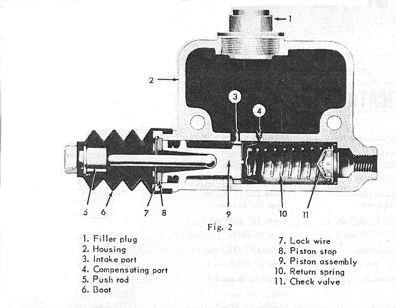 1ö bore MC, which was mounted on the frame below the driverĺs feet and has a one inch bore. These MC's are used on all brake systems in C/K type vehicles and many other models.
 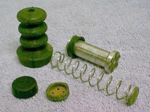 The internals, in order of usage, consisted of a dust boot, covering the single piston, a spring and a residual pressure valve (RPV). An explanation of the importance of the RPV, is below.
The 1" MC was the standard on many years and models, the only variation, being on the disk braked GT Hawks. On this application, there was no residual pressure valve installed on the piston return spring.
The internals, in order of usage, consisted of a dust boot, covering the single piston, a spring and a residual pressure valve (RPV). An explanation of the importance of the RPV, is below.
The 1" MC was the standard on many years and models, the only variation, being on the disk braked GT Hawks. On this application, there was no residual pressure valve installed on the piston return spring.
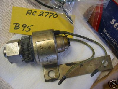 Anti-creep option was a brake holding feature used on cars with an automatic transmission. It consists of an electric pressure switch, mounted on the rear of the transmission, a solenoid in the brake line, a paddle switch on the throttle linkage. When the brakes were applied and stopped the car, the pressure switch was closed through low transmission line pressure.
 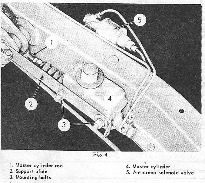 The switch, then provides current to the brake line solenoid and locks the line pressure. The vehicle was held in place and you could actually remove your foot from the brake pedal.
 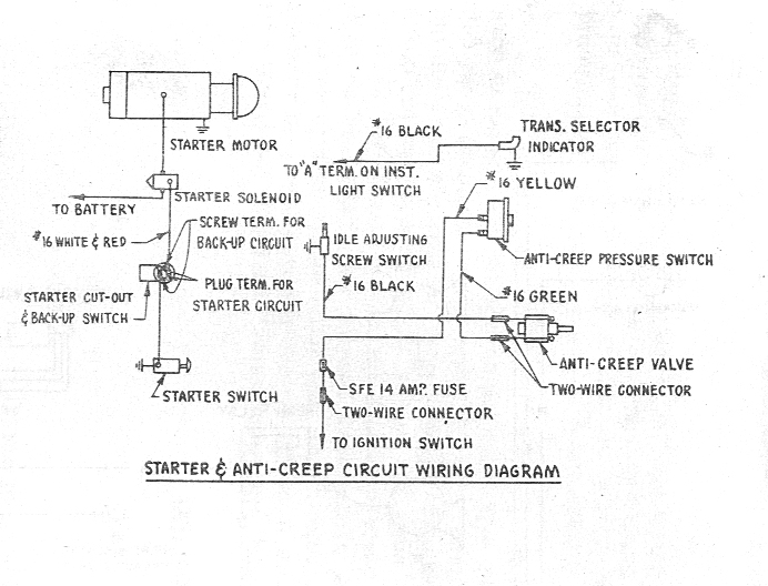 When the accelerator was pressed, a paddle on the throttle bell crank, moved away from a pin switch, opening the ground of the the solenoid, releasing the brake line pressure and allowed the car to move again. Anti-Creep was only configured to operate on the rear wheels and used a dual outlet at the Master cylinder. Anti creep switches could be ordered in 6 or 12 volt and were used as accessories up to 1964 (66?).
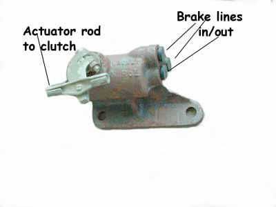 The NO-Rol or hill-holder is a device that locks the brake line pressure, using the action of the clutch linkage and is a simple ball check valve.
 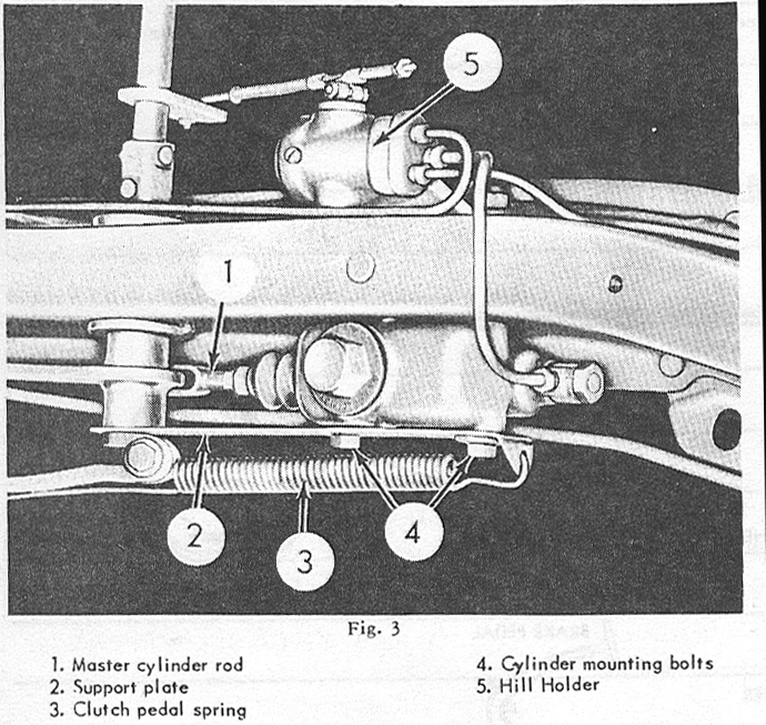 The brake line pressure is released when the clutch pedal is raised. The No-Rol unit is configured to operate on both front and rear wheels and the action is entirely mechanical. The unit has to be separately bled as part of the routine brake maintenance.
|
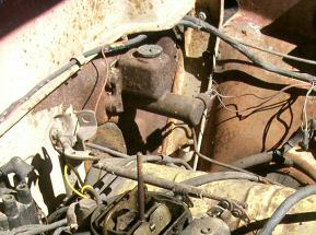
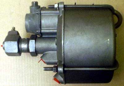
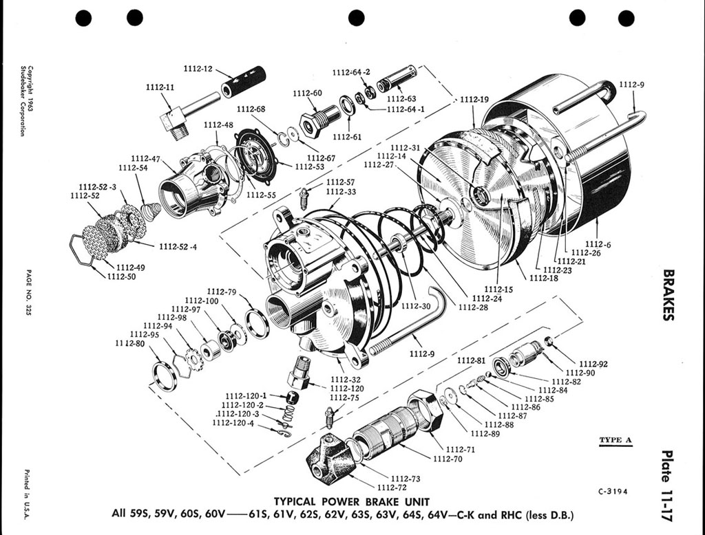
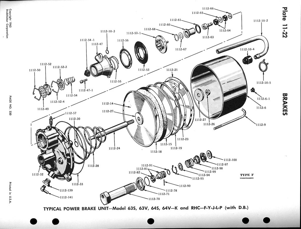
Power brakes Studebaker Power Brakes were introduced in 1955 and used the 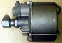 Bendix Hydrovac. This is a remotely mountable, power boost system, which multiplied dynamic input line pressure from the brake pedal, through a vacuum/diaphragm/plunger mechanism and was successfully used by many car manufacturers for years, including Cadillac, Mercedes and Ferrari. You can mount the Hydrovac anywhere on the vehicle and connect the input/output brake lines. The one downside to using this type of booster is that itĺs designed for only a single circuit brake system. The Hydrovac was used by various Studebaker models, until 1964. They differ in applications pertaining to trucks and there are differences in car applications also, such as the power drum brake unit (type A), as opposed to the disk/drum brake hydrovac (type F). Compare the two types. The main difference between the two is, the type "F" has a smaller diameter power piston and the power piston has different internals. Versions of the Hydrovac are still used on large trucks and variations have been developed over the years, which are still in use, today. Bendix Hydrovac. This is a remotely mountable, power boost system, which multiplied dynamic input line pressure from the brake pedal, through a vacuum/diaphragm/plunger mechanism and was successfully used by many car manufacturers for years, including Cadillac, Mercedes and Ferrari. You can mount the Hydrovac anywhere on the vehicle and connect the input/output brake lines. The one downside to using this type of booster is that itĺs designed for only a single circuit brake system. The Hydrovac was used by various Studebaker models, until 1964. They differ in applications pertaining to trucks and there are differences in car applications also, such as the power drum brake unit (type A), as opposed to the disk/drum brake hydrovac (type F). Compare the two types. The main difference between the two is, the type "F" has a smaller diameter power piston and the power piston has different internals. Versions of the Hydrovac are still used on large trucks and variations have been developed over the years, which are still in use, today. |
|
Along with the Hydrovac, Studebaker introduced a new power brake pedal. Functionally, the pedal had a much shorter stroke (see inset) and came to be called the 55% pedal. 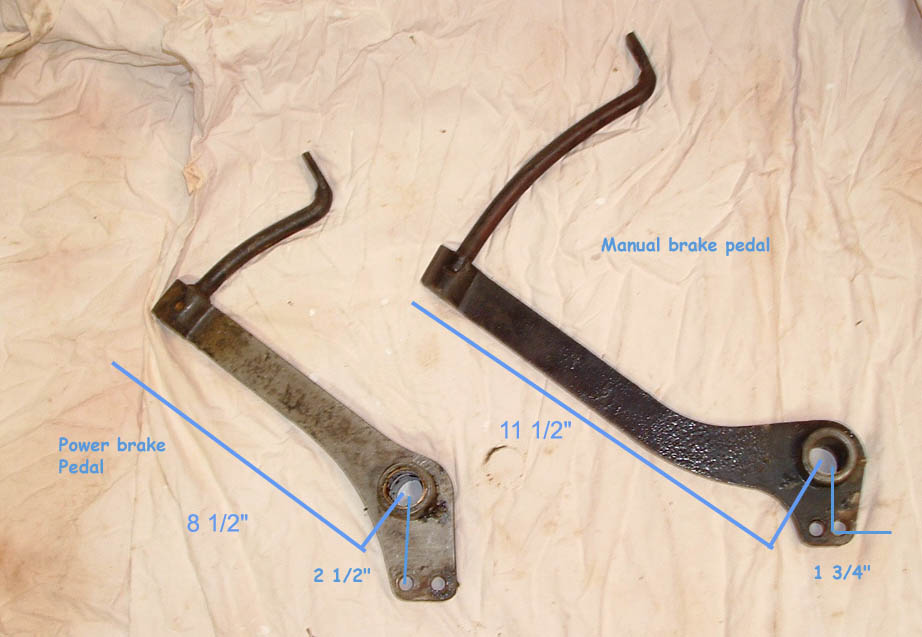 The power brake option was a welcome improvement, to the ladies, as they didn't have to lift their legs, too high, to apply the brakes. With a ratio of ~4:1, versus the ~7.5:1 ratio of the standard pedal, the mechanical advantage of the new pedal was significantly less than the mechanical one. In a power brake system, if your Hydrovac fails, stopping the car will require a great deal of pedal pressure. The power brake option was a welcome improvement, to the ladies, as they didn't have to lift their legs, too high, to apply the brakes. With a ratio of ~4:1, versus the ~7.5:1 ratio of the standard pedal, the mechanical advantage of the new pedal was significantly less than the mechanical one. In a power brake system, if your Hydrovac fails, stopping the car will require a great deal of pedal pressure.
From 1963 through 1966, a dual circuit master cylinder was used for drum braked sedans. It could be supplemented with a power booster mounted on the firewall.
The boosters for disk brake sedans and drum brake sedans are different. For the 56-61 C/K's and GT Hawks, the ONLY combination used was the underfloor master cylinder and the Hydrovac. The Hydrovac for a Disk braked GT Hawk is a different unit than the one used on any drum braked car. |
|
Master Cylinder Vent caps The Master cylinder cap on most single circuit Studebaker MC's is a direct screw-in type with a small hole for a vent and uses either a composition or copper sealing washer. 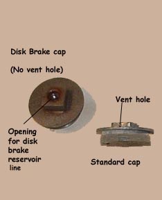 The vent hole is a poor design feature, as it allows moisture to come in contact with the brake fluid, which is highly hygroscopic (will absorb moisture). The fluid level drops as the friction surfaces wear and more fluid is required to move them closer to the rotating components, as they are adjusted through their lifespan. As fluid drops, moisture is drawn in with atmosheric pressure. The vent hole is a poor design feature, as it allows moisture to come in contact with the brake fluid, which is highly hygroscopic (will absorb moisture). The fluid level drops as the friction surfaces wear and more fluid is required to move them closer to the rotating components, as they are adjusted through their lifespan. As fluid drops, moisture is drawn in with atmosheric pressure.It is always advisable to change brake fluid in a Studebaker every two years, as this moisture will eventually saturate the fluid. Once past the the saturation point, it will remain as water, accumulating in a low spot, to eventually rust through the line or pit the wheel cylinders. 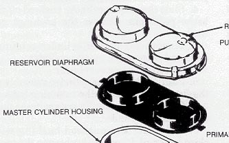 If you compare the caps with type newer master cylinders, you can see a rubber, diaphragm, cap gasket. The cap gasket will deform as the fluid drops to keep the container sealed and moisture out of the fluid. If you compare the caps with type newer master cylinders, you can see a rubber, diaphragm, cap gasket. The cap gasket will deform as the fluid drops to keep the container sealed and moisture out of the fluid.
Studebaker brake lines are generally 3/16, I.D. steel and travel from the MC to either a No-Rol/Anti-creep, or forward to a distributor block, at the main cross member, which tee's off to separate steel lines to a junction at each spindle, then to a flex line, and then to the wheel cylinders for the front brakes. The distributor block also contains a brake light switch and generally a line, along the inside of the frame to the rear wheel arch, down a rubber flex line to a distributor block on the rear axle and then steel lines to the individual rear wheel cylinders. On later cars with disk brakes, a remote brake fluid reservoir is mounted on the passenger side of the firewall. This reservoir was connected to the master cylinder, using standard steel/brass plumbing and connected to a special master cylinder cap. The cap on the remote reservoir was still vented to allow fluid drop and still has the deficiencies, noted above.
|
|
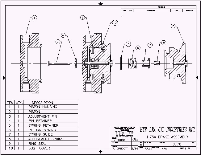
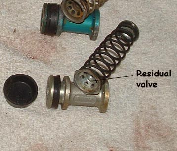
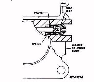
Residual Pressure Valve In the Studebaker underfloor Master Cylinder, the RPV is a small tin hat with holes and a rubber diaphragm, on the output end of the spring.( see insets)This valve serves two purposes. When the brakes are released, the return springs on the shoes, having a calibrated pressure, pull the shoes off the rotating component. As the springs retract, fluid is forced back toward the MC, under pressure from the springs. As the spring relaxes, the line pressure diminishes. At approximately 10#, the RPV in the MC stops any further retraction, resulting in approximately 10# of brake line pressure, after the pedal is released. This line pressure maintenance keeps the return springs from fully retracting, in order to keep more fluid in the cylinder. This prevents the MC from having to push a full volume of fluid out, next time, to engage the brakes. Also, in the case of an underfloor MC, prevent the weight of the fluid draining back to the master cylinder reservoir, where in the case of the Studebaker type, would overflow through the vent hole. In a case where fluid drained back, the next time the brakes were applied, the pedal would have to be pumped up to fill the lines.
|
|
Disk Brake cars: (edited June 2008)
(11)
The rear drum brakes on a Disk Brake Studebaker are "servo, non-self energizing" and were used to counter the requirement for a proportioning valve. A self-energizing brake, upon application, will 'wind-up' inside the drum and increase the stopping power significantly moreso than the non self-energizing - Notes on Oddly enough, there is no residual pressure valve in the MC either, to compensate for return spring pressure and there's no check valve in the Hydrovac for this purpose. The rear drum adjustment, using the locking eccentric, must have precise enough characteristics, that forego a requirement for it.
Stude Hawk (Factory) Disk brakes never used an RPV on the front for two reasons. Least of them is the Dunlop disk brake design, which incorporates a
(12) Turner GM style disk brakes, as all modern types, have no mechanical pad retraction mechanism. What is designed into the piston is a seal that will deform as the piston moves with the application of the brake pedal. When the pedal is released, the seal returns to shape and helps pull the piston back. Not that this is a disparaging point, but the GM & other floating caliper designs only allow the piston seal to deform against the cylinder wall on application. When the brakes are released, the seal straightens, inducing a bit of clearance, along with releasing pressure on the piston/pad. That, plus the slight amount of wheel bearing wobble, is what allows free rotor movement. Over time, the seal will wear down and not retract as well, causing the pad to drag on the rotor. Here's where the residual pressure valve sausage is made.... If you have a drum braked car and you change to the Turner system, your dual MC may have RPV's in the port(s). You have to remove the RPV from the port serving the disk brakes. If you have a Stude Factory disk brake car with a firewall MC (Lark/ Avanti) then your single MC should be adequate, as is. If you change to a dual MC then check the DB port for an RPV and remove it, if found. The factory rear brakes for a Disk brake car can be used with Turner system but may require an RPV. Try it without one and see if your pedal remains high
Whether or not, you use the original single Stude single MC or a dual aftermarket MC...
If you do it like this, and have a reservoir on the firewall, you'll never, again, have to fool with getting under the floor to check fluid.
|
|
TURNER Dual Master Cylinder Bracket (15) 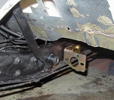 Installing a Turner Dual Master Cylinder Bracket (left) allows you to replace the Studebaker single circuit master cylinder with an, up to date,
 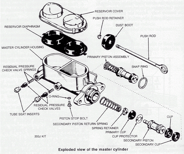 dual circuit, master cylinder, which goes al long way toward improving safety in your car. dual circuit, master cylinder, which goes al long way toward improving safety in your car. In a dual circuit system, if either one of the circuits get damaged, you can manage a safe stop using the other circuit. Installation instructions come with a list of recommended master cylinders, to use on the bracket. Others have been found, with nice features, including remote fill capabilities. The things you have to remember, is that 1) these recommended master cylinders were used on applications other than Studebaker, so they have to be modified. 2) none of them were designed to be installed under the floor, of a Studebaker, so there may be issues that were not found initially. One of these issues involves the filler cap on some MC's, others involve the MC contacting a body brace, or crossmember. The one item that is a sore spot and never understood, are residual valves. These are small rubber check valves, installed on ALL drum brake systems to maintain a certain level of fluid pressure in the brake lines. Turner's kit comes with Wilwood Residual Pressure valves. Depending on your application, you have to install a 10# valve on the lines to drum brakes and a 2# valve on lines to Disk brakes. To modify ANY master cylinder, you have to open the unit and inspect if there are small rubber valves mounted in the line ports. If there are, they HAVE TO BE REMOVED and the unit reassembled with out them. 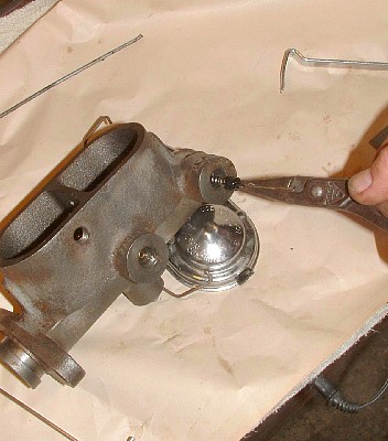 Here is a web page that describes how to accomplish the removal of residual valves ----->
(16) After you have modified the master cylinder, you have to "Bench Bleed" it, before installing it on the car. This entails placing it in a vice and connecting the line ports to the reservoir, then slowly pumping the unit with a blunt tool to emulate the brake pedal action. This will replace all the air in the unit with brake fluid, prior to installation and helps greatly in getting the brake lines bled on the car.
Install the unit and then, plumb the NEW (Turner) residual valves as close to the master cylinder as possible.
|
|
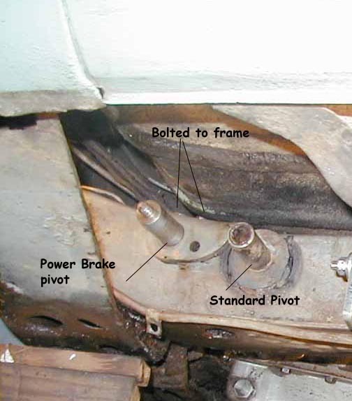
Variations on the theme (17) You have drum/drum brakes and want to improve things.............. The first thing you should do, is inspect your components, to see if you have a power brake pedal, and if so, swap it out for a standard pedal. No other ONE thing will assure you more safety than that long pedal. Hydrovacs work satisfactorily when they are in good shape and maintained well, or if they have been rebuilt by a reputable shop. To those of you who swear by a Hydrovac, I won't argue your position, but for 45 years, my observation, is that "I've never met a Hydrovac that I liked". It has often been stated that you do not need a hydrovac to have good brakes. You certainly cannot have good brakes if you have a marginal Hydrovac and/or a power brake pedal. If you install a dual circuit master cylinder, the Hydrovac can only feed one of the circuits, since it's only designed for one.
(18)
|
Bendix Disk brakes ( Excerpts from the 1961 SAE Paper presented by Studebaker) Avanti Disk Brakes |
DISK BRAKES
|
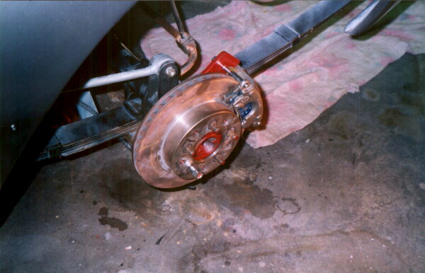
(20) Disk Brake Turner Disk Brake (DB) Kits are designed to enhance the braking ability of your Studebaker, as well as introduce components that are readily available and very affordable. Changing the brake system requires an understanding of some standard components, particularly, the cylinder sizes, mechanical function and residual valves in the master cylinders. Included in the Turner disk brake (TDBS) kit, are 2 new residual valves, one red (10#), the other blue(2#). If you elect to remain with the standard Studebaker single master cylinder you must, first, disassemble it and remove the residual pressure valve (RPV) from the front of the piston assembly. This is a good time to rebuild the unit anyway. The RPV is the small tin hat, with the rubber cover, at the front.
If you elect to upgrade to a dual master cylinder, you need to remove and discard the internal residual valve from the Dual MC unit, you choose, and install the supplied red and blue valves in the brake lines, to the specific wheels. There are exceptions to the front RPV as stated above.
The Turner DB kit can be used on either a drum/drum car or a disk/drum car. There are differences in applications though.. The Turner DB kit can be used with or without power brakes. |
|
(21)
|
|
(22) (020705)Turner DBS with a Hydrovac Various opinions on this, due to the difference in supplied line pressure. The resolution would be to balance the line pressure in both the front and rear, using a combo valve. To install a Turner (Disk Brake Kit) (dual MC) on a Disk brake car with the Hydrovac power boost - Use an 11" standard pedal only. Don''t even think about using a short (early) PB pedal, as Disk brakes require much more force than the early PB pedal will offer, plus the factory disk brake option included NON-self energizing rear drum brakes, which alleviates the requirement for a proportioning valve. Fluid reservoir is in a remote tank on firewall, dual MC front fluid line routed to Hydrovac, (then to a 2# residual valve (See NOTE *1)), then to front wheel cylinders - rear MC fluid line routes to 10# residual valve, then to rear Wheel cylinders. Brake light switch can be at Hydrovac or tee'd inline if new lines are run.
|
|
(23) Avanti Disk brake to Turner Disk brake (MC above the wheel cylinders) Master Cylinder - 63-70 Avanti (4-bolt Replacement, dual circuit - mid 70's Chrysler. NAPA #36307. Turning Wheels, April 2001 (Jim Turner , Jan 2003)
(24)
(25)
The J65 Master cylinder was designed with a low pedal ratio for reduced free travel and a firmer and higher effort pedal for the high performance buyer. There was a GM bulletin (Bulletin # 84-88; Section 5 (V); Date: March 1984) stating that people hated the feel of the J65 brakes so they made available the J50 Master cylinder as a replacement. So in pre 1990, when GM customers used to come in and complain about their J65 disk/disk brakes...GM would actually swap on the J50 disc/drum master cylinder. (the one that was on my car) In 1990, the J50 became standard equipment for the disc/drum and disk/disk cars.
It is recommended to find an 89-92 disc rear. Those are the best, and you can re-use your existing J50 (disk/drum) master cylinder. Grab the prop valve too. GM still sells 'em for $80.
|
Footnotes
NOTE:2 )Even if you have a remote reservoir, above the master cylinder, AND front disk brakes, you will need a front RPV. wf:1 - Wayne Flowers (wayne@zianet.com) Albuquerque, NM