
Bob's Resource Website (2007)
Studebaker Power Steering Ram Rebuild - How to
by SBCA96/Tom Rautio, Santa Barbara, CA
|
I decided to break this down into sections, rather than do them all
together. This is the first of 4 parts, the subject is a 1963 Avanti
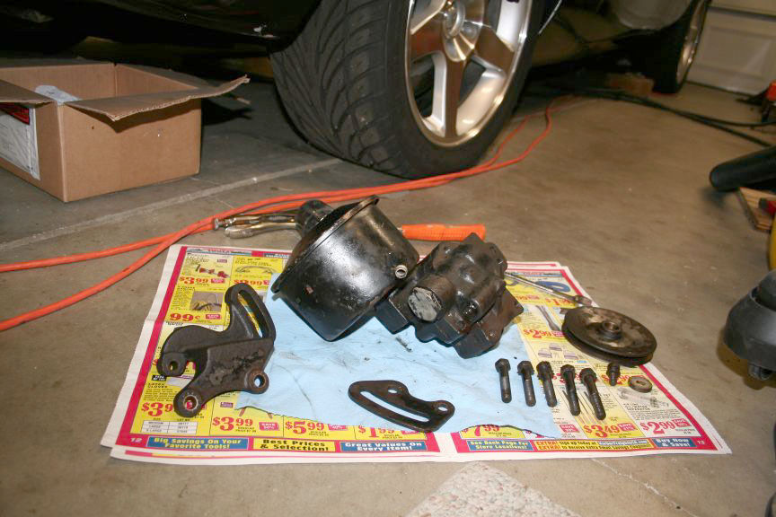
but the basics can be applied to most early 60s Studebakers. I pulled the pump off a couple months ago after blowing a seal, the hoses and just about everything else is old & tattered. If the pump hadn't failed, the pressure hose was a close second, as the hose at the pump end had passed its expected life years before.
|
|
|
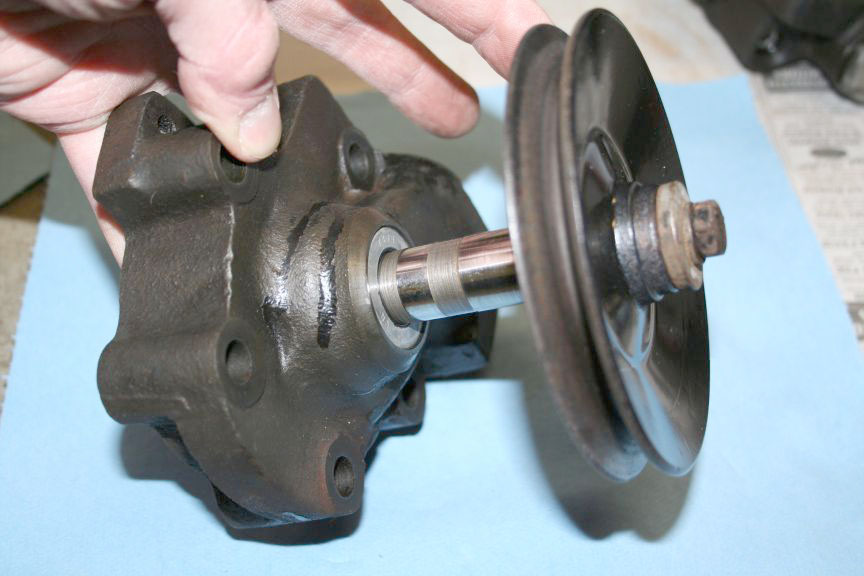
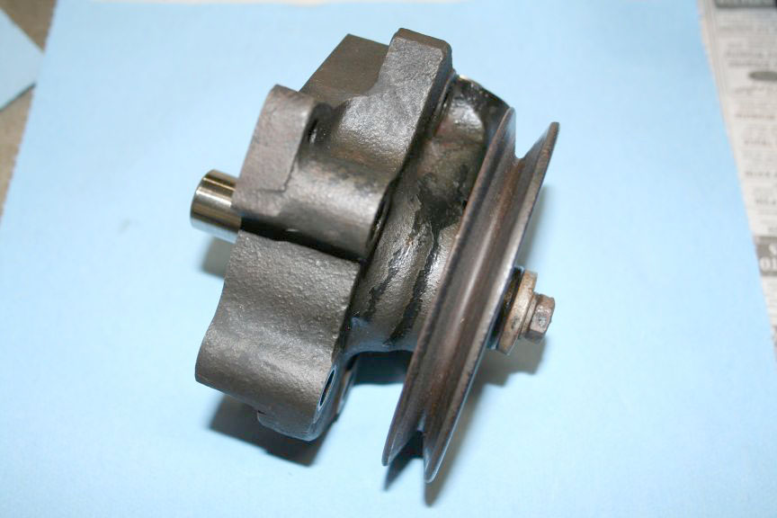
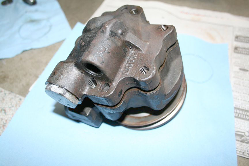
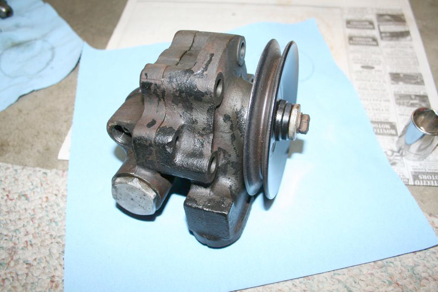
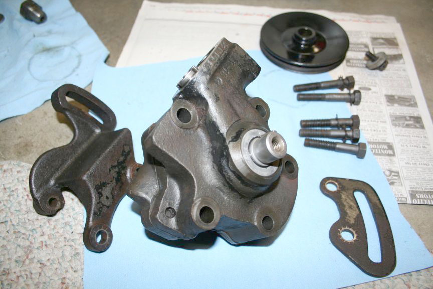
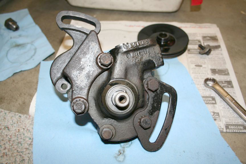
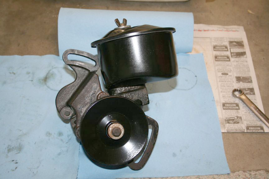
| Tonight I started cleaning and disassembling the pump. The pulley is the "keyed" style, with a thick washer and bolt. A 1/2 wrench is the requirement here. I used a pair of vice grips and grabbed the outer edge of the pulley, and rotated the pulley until the vice grips hit up against the pump case. I hit the wrench with a rubber mallet and it came loose (Poor mans impact gun). Once the bolt was loose I took hold of the pulley and pulled it in & out which worked it loose from the shaft, your level of difficulty may vary. Next was the pump case bolts, which hold on two of the mounting brackets. They require a 9/16 wrench, I used the same technique for these(rubber mallet). A bit more cleaning was required once the brackets were off. This is as far as I got before getting cleaner into an open wound on my hand, this pretty much ended my fun for the evening. It seems the case is held together with dowel pins, any tips as to where to pry? Nate? Mike M? | 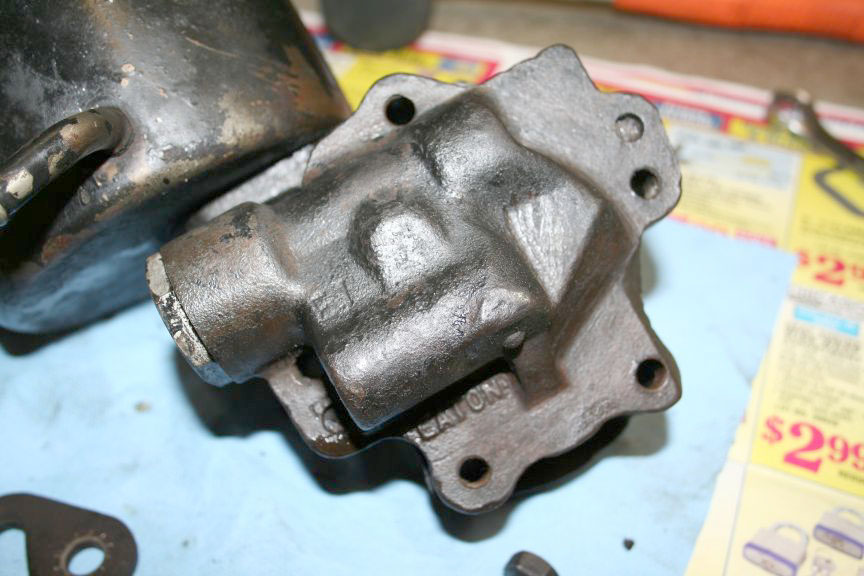 |
|
|
Dont pry on it, just light taps with a hammer around the case. There are many surprises inside, and they all go a certain way. The O rings are probably burnt, with chunks of fluid helping hold it tight. Be patient, the last thing you want is a parts in your lap.
MIKE |
I don't remember any special difficulty getting it apart. Mine looked awful inside. The drive pin, that keys the rotor to the shaft was breaking up; and the rollers had dug into the end plate. I figured I would clean it up and use it until I found another. Small Fords used the same. I made a new drive pin, and sanded the end plate flat. That was about six years ago. It's still working great. I made the mistake of not doing the whole system at the same time; and had metal particles in the ram, that later went everywhere. I trapped them, over time, with a magnet in the reservoir and a few fluid changes. You can plug the fitting on the reservoir, and run the return hose into a bottle, to flush the system. Just keep filling the reservoir. Be sure to use a grommet and washer, in the lid, that allow the reservoir to vent. Most kits contain parts for Fords that vent from the fill stack. They do a nice job of sealing the Stude reservoir, until it gets hot and forces fluid out. Mike M. |
|
|
I grabbed a Ford top off of a boneyard car that had the fill cap and dipstick on it.. Jeff |
||
|
Yah .. I had the WHOLE pump from a Ford, with the cap, dipstick & all,
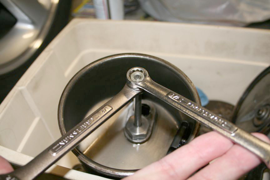
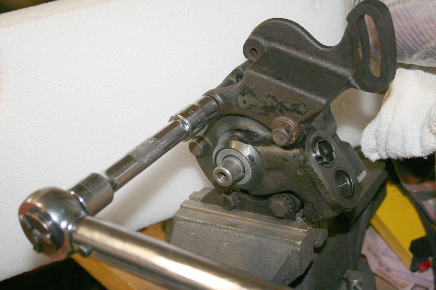
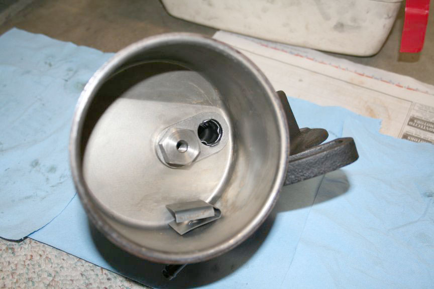
that went to the scrapyard with the Lark parts and engines. OK, this weekend I was finally able to continue taking the pump apart. According to the instructions, you remove the lid, and put two nuts on the shaft, tighten them against each other and unscrew the shaft : |
|
|
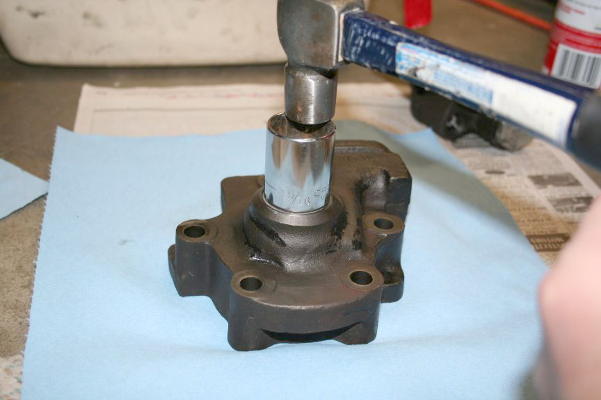
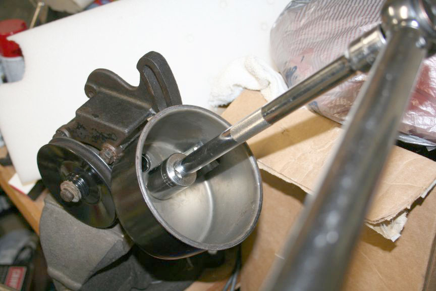
| After the shaft is removed, there is a bolt in the bottom that has a tapped hole for the shaft. That is removed with a 1 inch socket. I used a rubber mallet on the wrench to "negotiate" it loose : | 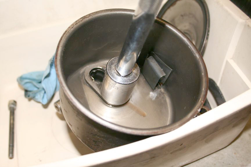
|
|
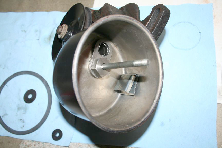
| Here is the bolt removed : | 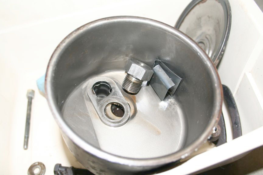
|
|
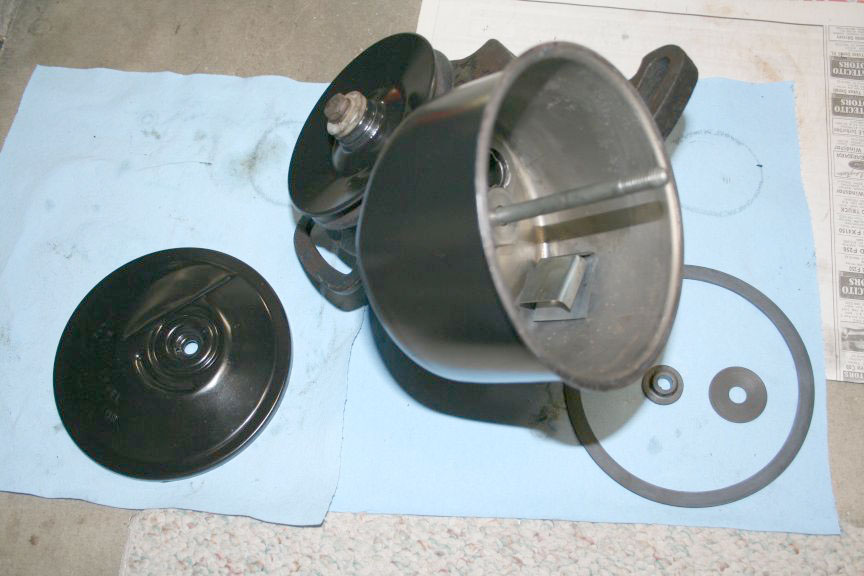
| The reservoir just lifts right off with the bolt out | 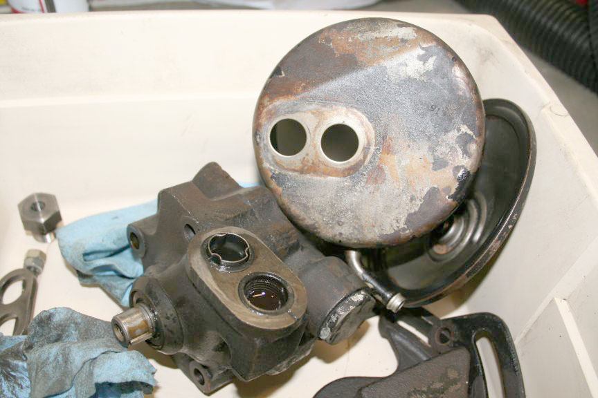
|
|
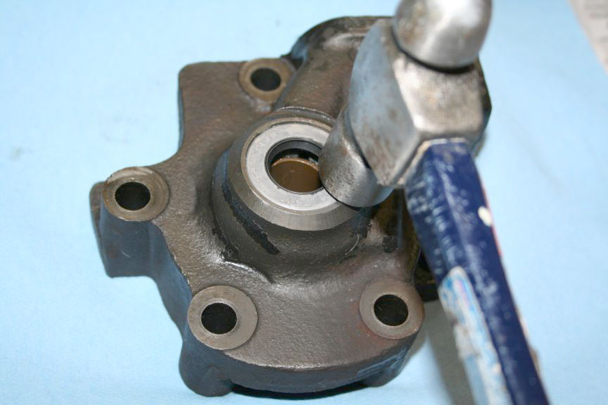
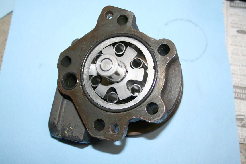
| Tapped on the sides with a small ball peen hammer, took a couple solid hits but the case started to separate. Once I got a gap, I put a wide blade screwdriver between the halfs and carefully twisted the handle. I made sure to pry near the dowel pins, and went back & forth between them to separate the case evenly : | 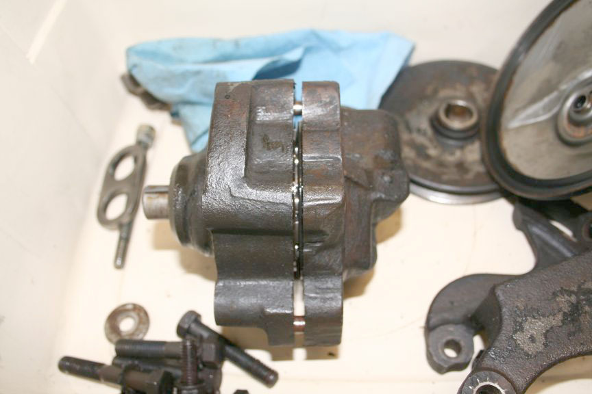
|
|
| Tip the case onto the shaft side to keep the guts from falling out : | 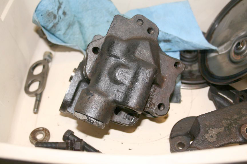
|
|
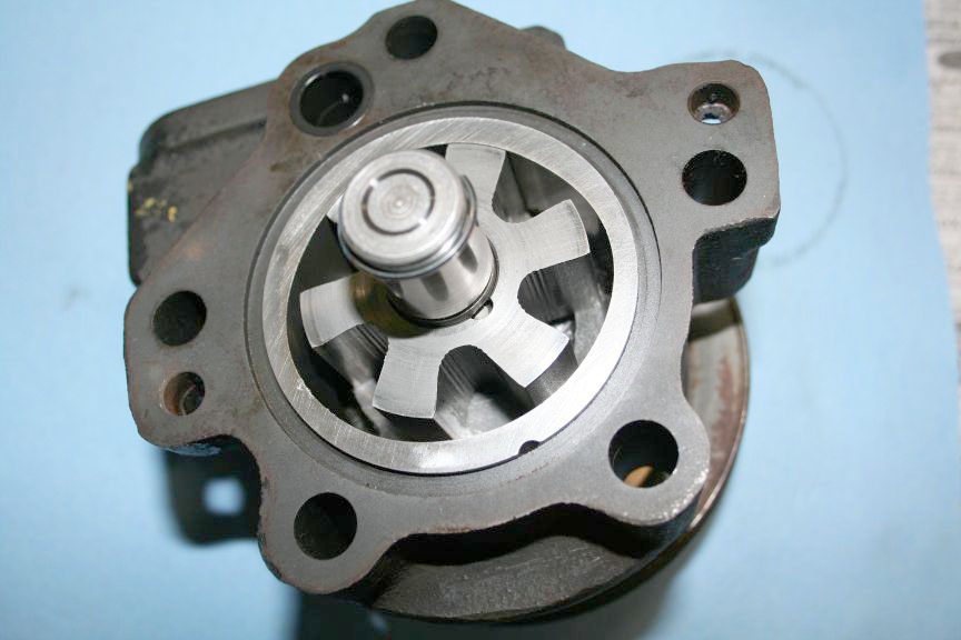
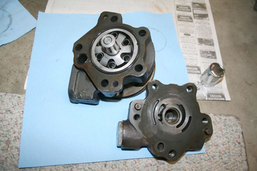
| Lift the vane side off the housing side : | 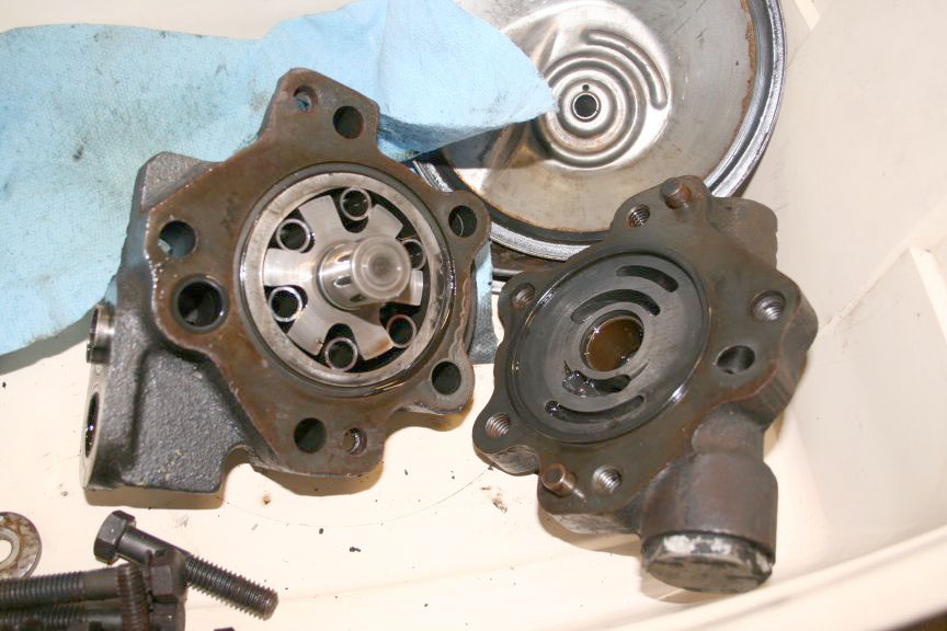 Thats as far as I got today. Doesnt seem like much I know. |
|
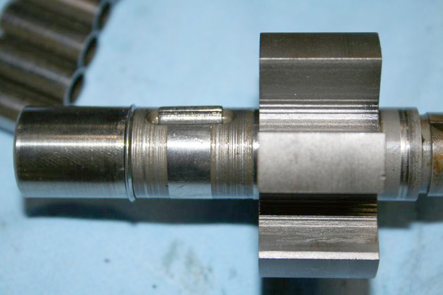
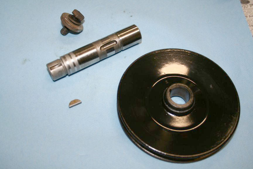
| Back to mess with it a little more tonight, pulled the shaft out of the housing : | 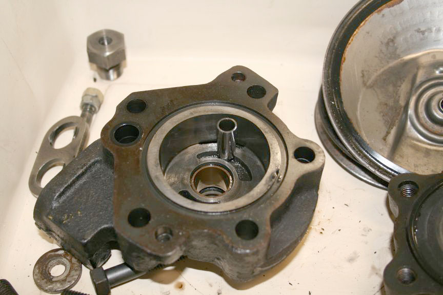 Wiped of the yucky fluid : |
|
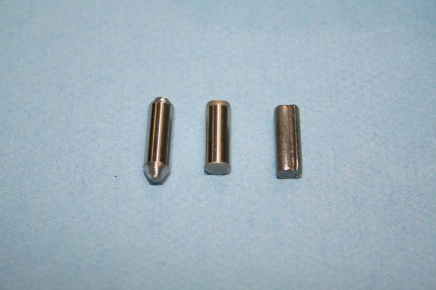
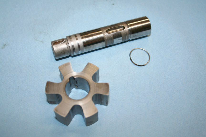
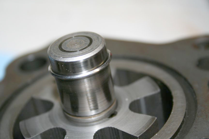
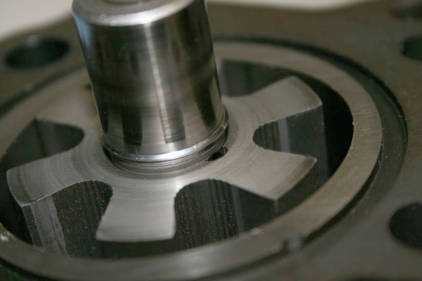
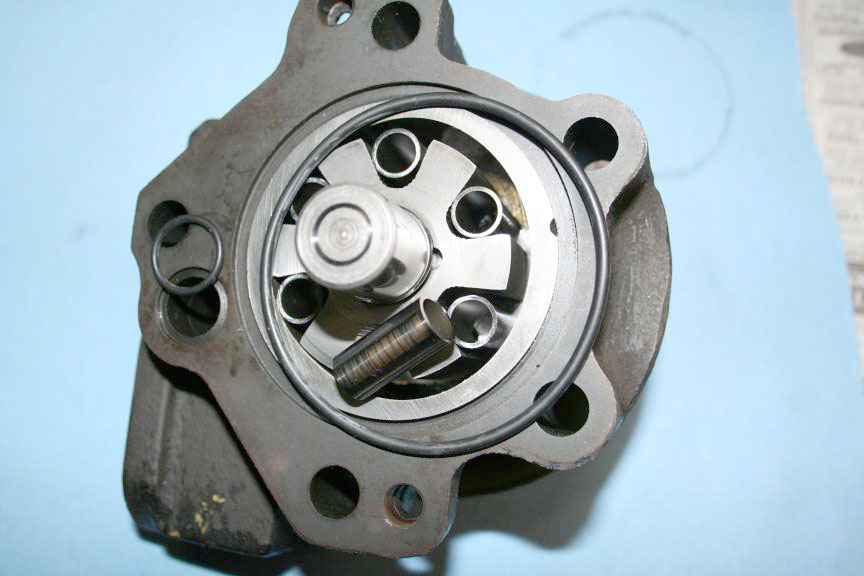
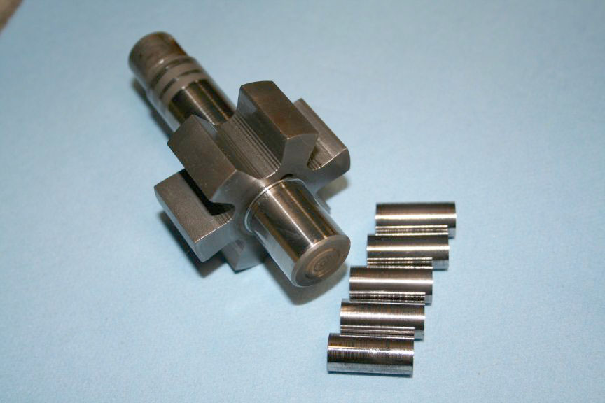 The gear part slides on the shaft and is held in place with a snap clip of some sort, and a dowel pin.... |
 (any guesses as to material? Mine has a ridge on it - I think its supposed to be round) : |
|
|
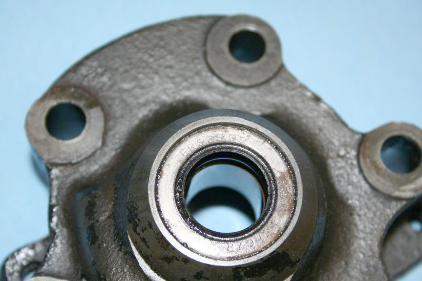
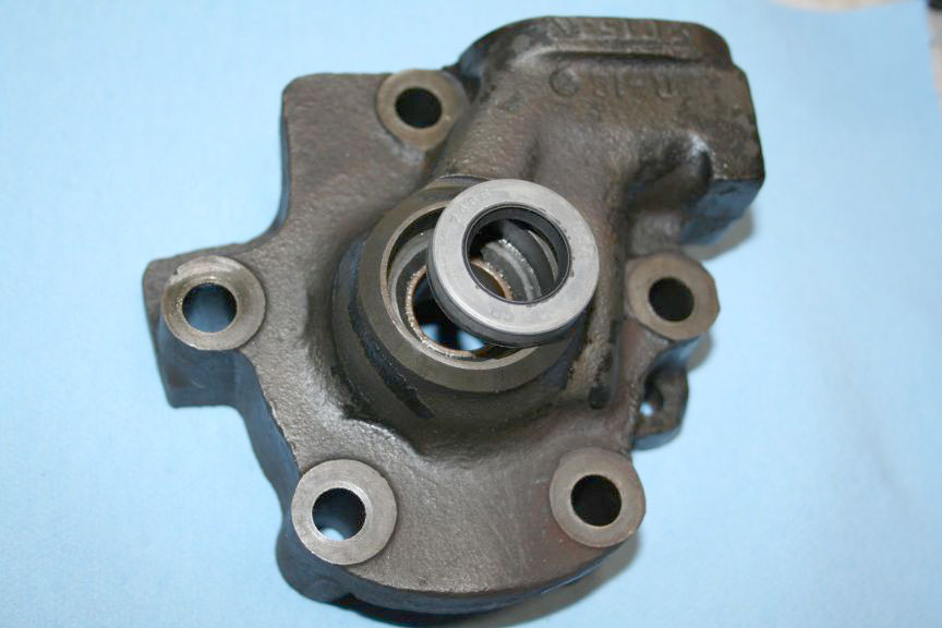
 Here is the main seal in the housing, its a nice double seal with a good amount of surface area : |
|
| Grabbed my handy dandy seal puller I got from Harbor Freight (if you dont have one of these, you are missing out - makes life easier). | 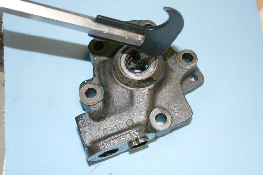
|
|
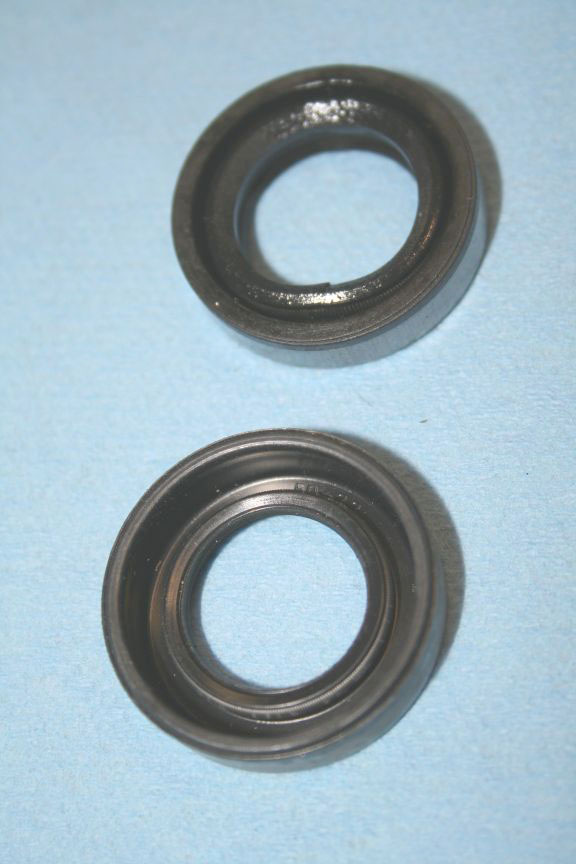
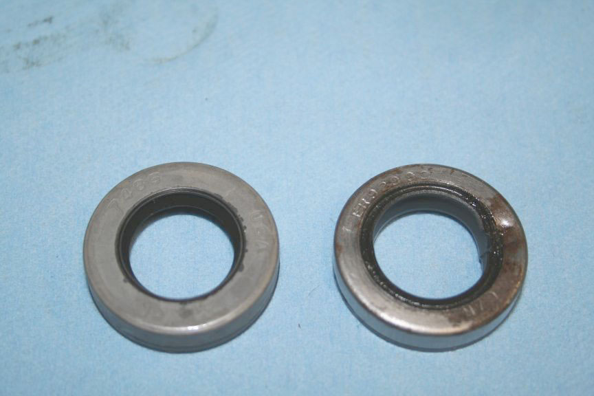 I wasnt too impressed with the seal that came with the Stude Int kit, it was lighter duty, and less sealing surface area. outside : |
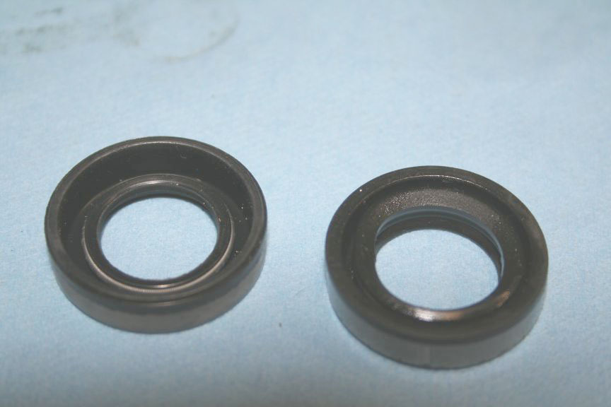 inside : |
|
| I wonder if the Ford replacement part is better?? I think I will see if Napa can cross reference this number. Tom |
|
|
|
When I rebuilt the PS Pump on my 60 Lark I bought the kit from SI, but thought the seal looked inferior, so I went to my FLAPS and asked for a shaft seal to fit an Eaton PS Pump for a 60 Ford and it was an exact match to the original. Studebaker Fever / 60 Lark / 51 Champion / Phil / Arnold, Missouri |
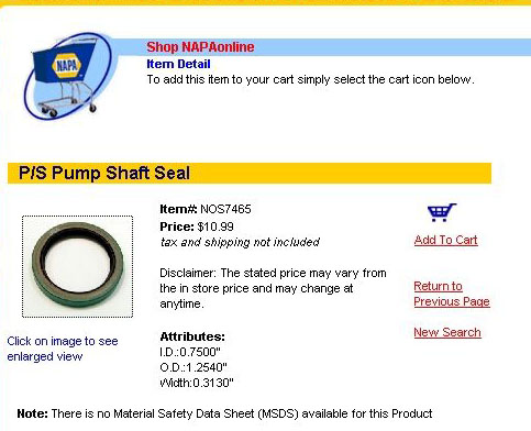
(NOTE: Edited for brevity- July 2009) The shaft seal number is NOS7465 from NAPA. One comes in the kit from S.I. but if you mess it up, get one from NAPA
I.D.:0.7500" (Info, courtesy of Dan White) |
|
|
My old CR Bearing/Seal book calls for: '63-'66: CR 7465 '60-'62: CR 7440 '58-'59: CR 7475 Paul |
Just to give you guys a heads up... Chicago Rawhide, as a company name, is no more... After over 130 years of being a great American manufacturer, the current owners (SKF) put the SKF name above all else and now it is called SKF Sealing Division.. (SKF is a Swedish company and they have owned C/R for about 18 years now).... But... The SKF sealing divisions part numbering system is based on shaft size. So, that part number 7440 means that seal will fit a .744" shaft.... and that 7465 seal will fit a .746" shaft. You can still have variants of the number and it cam mean a few things like single lip, double lip, nitrile rubber, Viton, etc. So you really can't just grab the numbers close to that one. SKF seals are partnered up with NAPA, so that makes it a bit easier to work with. Hope the info helps... Jeff |
|
|
OK ... I was doing some research while everyone apparently was also. I
first went to Napa with the part number and he crossed the CR. I did
not get the first one you found Nate. He found the second one right
off, and it showed Avanti as the application, as well as 62-67 Fords. NOS7465
Unfortunately, its a special order, and they charge for shipping. They
did say they had one of the store about 100 miles north. I passed on
it for the time being, figuring I would follow up on the Ford numbers.
|
|
|
|
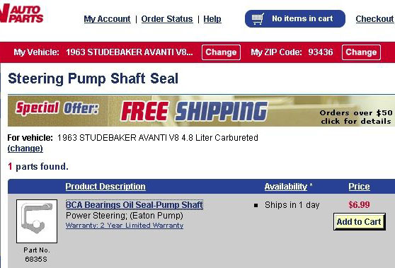
But this doesnt help much, since its special order, so I tried looking
on the Autozone website, no listing for Stude. So I thought I would try Kragen, they had a listing for Stude : |
|
|
| So I tried 1964 Mustang, it was the same number! : | 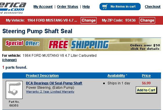
|
|
| So I went back to the Autozone website, but no listing for Mustang. So I tried 64 Fairlane and they had a listing. | 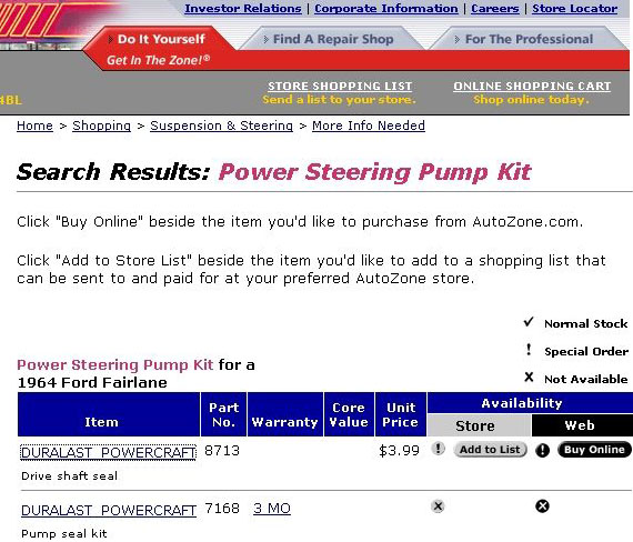
|
|
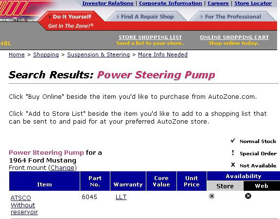
| But that doesnt mean that the Mustang and the Fairlane use the same part, I had to confirm that, so I looked up the whole pump, and even though they dont carry them, they had a number - which was the same. | 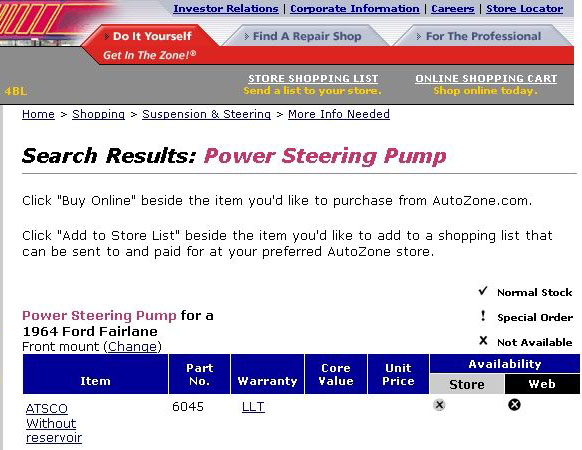
|
|
|
So we can "assume" that the Autozone Fairlane seal should work. Its
anyones guess if its the "good" one. I will see what the chance of
Kragen getting the one above in. Thats what I found so far!
Tom |
|
|
|
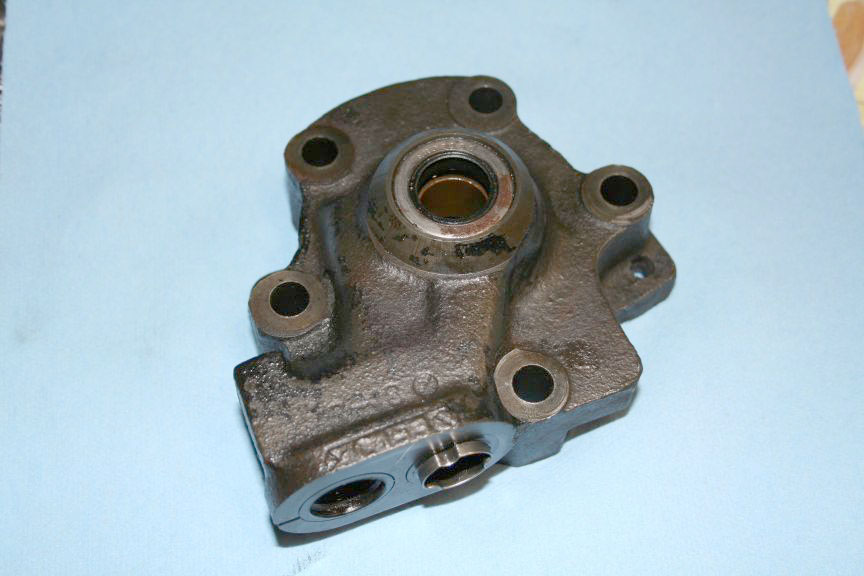
om,
I don't mean to jump ahead in your procedure, but as the front half of the pump body is laying there, you can remove the outer race just by using a couple of fingers of each hand to reach inside and slide it out. It's not an interference fit, should slide out easy. Be extra carefull to notice the tiny pin in the lower corner of of the housing where you just removed the race from. It is very easy to loose . Ask me how I know! Again...didn't mean to interupt, but some might not think the race comes out at first, but during the cleaning process is when you would discover this, and that is when the pin comes up missing. Just trying to help. Great job so far!!!
Dan Miller / Atlanta, GA |
Thanks Dan, yes that sleeve IS a slip fit! I thought I was losing my
mind (might still be!) when I noticed the housing "levitating" above
the piece of paper I set it on!! I picked it up and like you said it
was hanging out. The pin was still there. I still need to familarize
myself with all the parts to figure out what I am replacing. The kit
doesnt include bushings, so those are staying. I will try the Kragen
down the street after work for that seal.
Tom |
|
|
UPDATE: Wish I had better news, I drove all the way up to San Luis
today to look at that Napa seal and its the same one I got on the kit.
I got another possible number though, sounds promising but its special
order only. I might be able to cross it to another brand seal?? The
number is a 7449 : I.D. : .75" O.D. : 1.254" Width : .375" It also lists as being a different style case. The San Luis Napa has internet connection and pulled up this forum to check Nate's numbers. I wanted to make sure the above (7449) hadnt been posted. He looked at the pictures I posted of the original seal, and said it looked like the same case as the 7449 seal, where as the 7465 is different. Tom |
||
|
So far nothing but dead ends. It doesnt look like the OEM seal is
made anymore, and the one in the Studebaker International kit is the
best replacement available. That's depressing, but I guess such is
life. The Napa ordered the 7449 seal, and it has the SAME thin seal
area that the S.I. seal has. Each seal I have found has the same
type, just a thicker or thinner case. I was going to bring the OEM
seal by for the guy to look at personally, but it looks like it is
what it is, and the pump will go back together with the thin seal.
Tom |
||
|
Got out there to do some more on the pump today, during the week I had
the lid and reservoir soaked and sandblasted and then painted them. I
gave up on the seal search, just going to use the one I have. I seem
to remember Mike posting up some info on how to install it without it
being damaged, but I tried search and cant find it now. If memory is
right, you remove the gear and the snap ring, pound the seal into the
housing, and push the shaft in from the outside (with the pulley on).
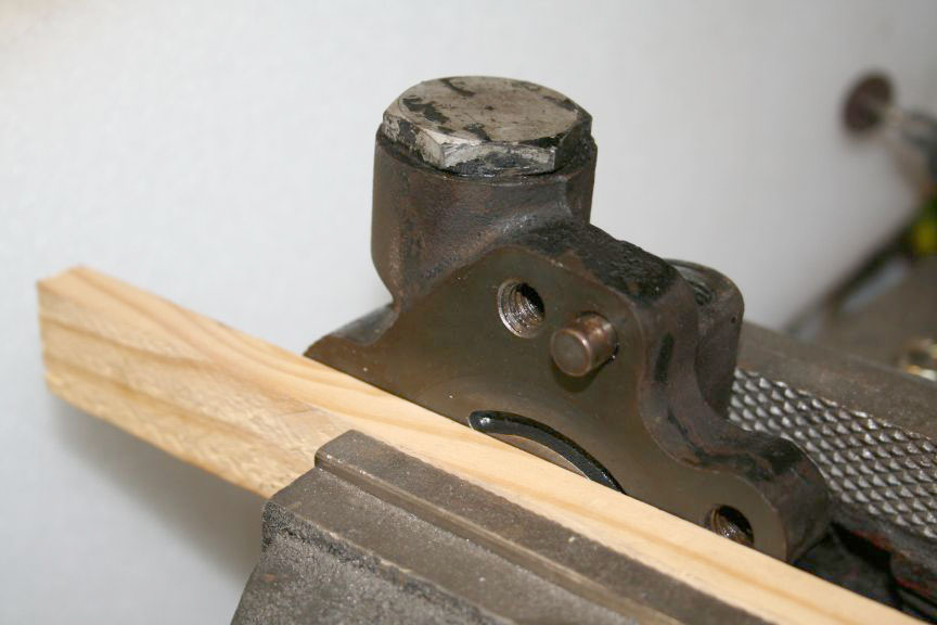
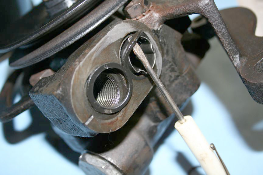
Here is how I removed the valve assembly, in a vise with a piece of wood protecting the o-ring surface from the jaws of the vice : |
|
|
| As far as I can figure out, the kit comes with a couple seals you dont use, I laid them out on a towel .. and labeled them. | 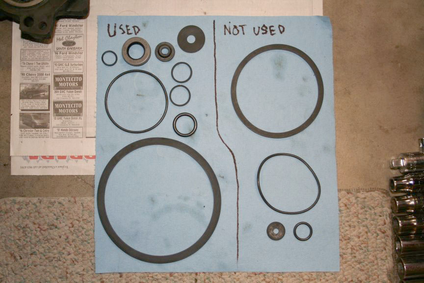
|
|
| Here is the valve out of the housing, and the fat o-ring from the kit. | 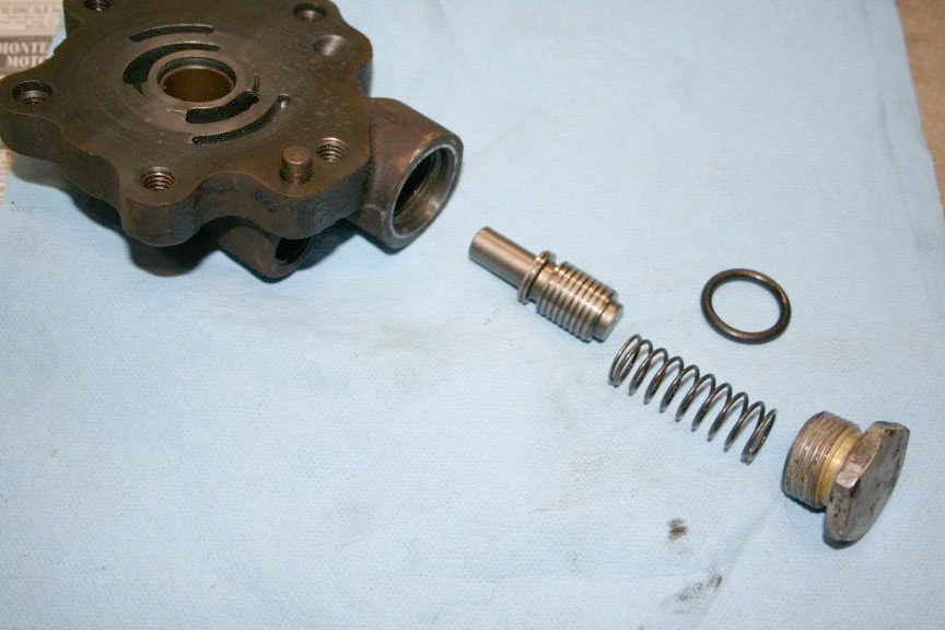
|
|
| Installed o-ring, I just lubed it, and rolled it gently over the cap threads, that should be OK. | 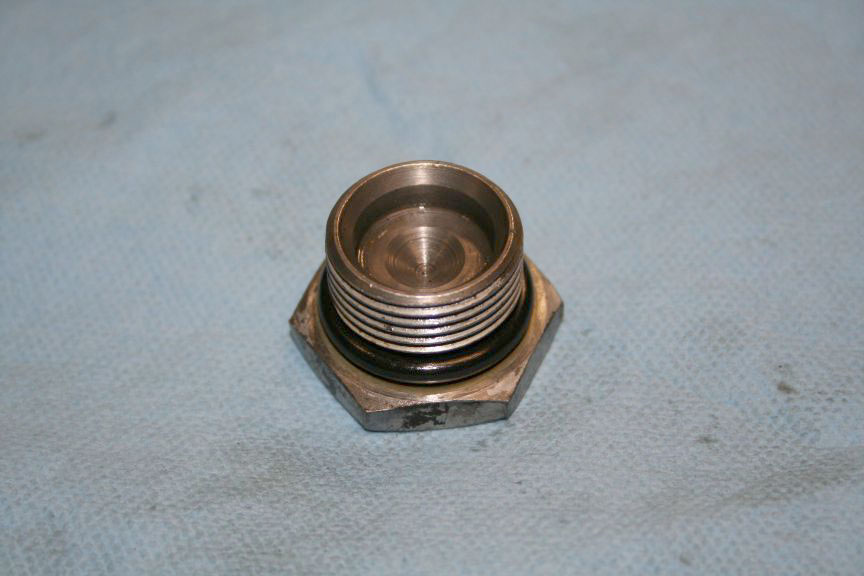
|
|
| Added lube to to and tightened it back into the housing using the wood block as in the above picture. | 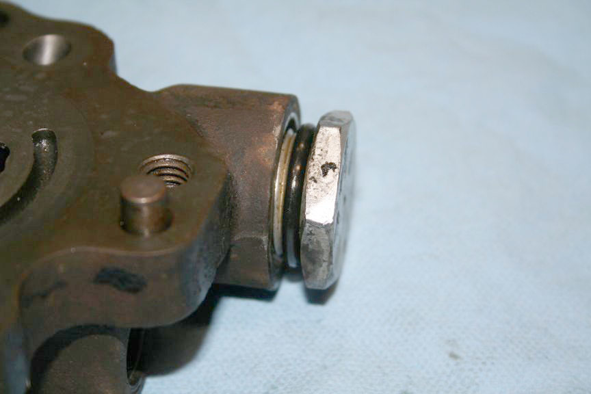
|
|
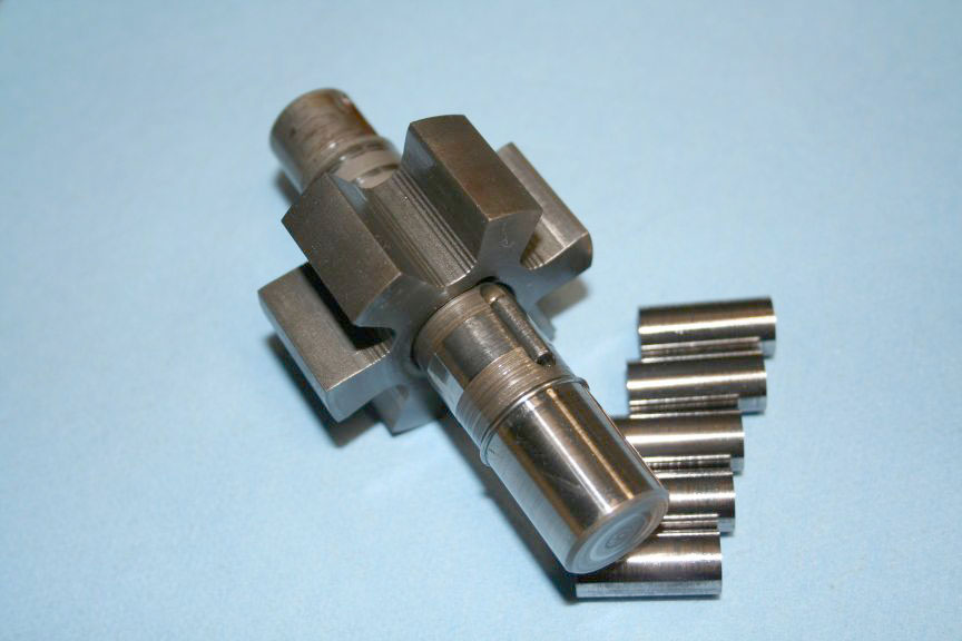
 This worries me, the shaft is scored, I noticed it before, but now I wonder of its OK. The pin is crushed like you mentioned Mike. I think its around a grade 5 or grade 8 pin? |
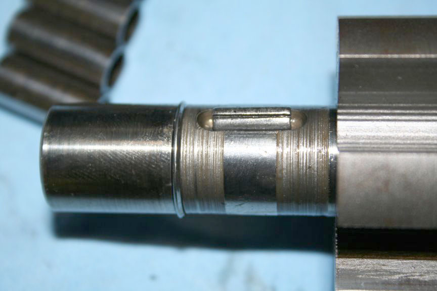 I could probably buy a shoulder bolt and cut the head and threads off. I will check with Napa. See any problem with using this shaft? |
|
|
Go get yourself a 99075 Speedi-Sleeve from SKF (formerly Chicago-Rawhide), or a 99075 Redi-Sleeve from National. Follow the instructions about installing the sleeve and removing the installation ring. https://www.alliedbearings.com/mfg_prod/seals/cr_speedi/cr_speedisleeve_install.pdf You may need to modify it a bit, but if it can save your shaft.... They are only eleven thousandths thick, so your seal will ride on a good shaft surface (centerless plunge ground).. These have saved a lot of shafts in the world.... https://www2.chicago-rawhide.com/speedi_sleeves.htm Jeff |
The grooves in the shaft, at either end of the cutout for the pin, don't matter. That's an area that doesn't contact anything when the roller carrier is slid over the drive pin. The grooves are the original finish. The carrier comes off the shaft easily, with the snap ring removed. What was left of my original pin looked like it had once been smooth and round, with rounded ends like the cutout in the shaft. Maybe it's supposed to shear easily, if the pump jams. I think I made my new pin out of the smooth end of a drill bit. I rounded the ends like the original; and made it a little longer, to almost fill the cutout. I may have used a nail; which would be a little softer. By the way, the pulley uses a conventional half moon key. Mike M. | |
|
This is a great post! I am looking forward to rebuilding mine. Tom when are you doing the actuator valve? I need some tips and step by step pictures on that one too! 1964 GT Hawk soon to be R2 Clone |
Thanks for the input Mike and Jeff, sorry I should have made it more
clear that the grooves are not at the bushing surface, but under the
gear (which doesnt rotate). It does seem like the material of the
pin is soft, the instructions say to replace it (easy to do back when
the car was new!).
Was I correct in the install of the shaft, after the seal has been put into the housing? I have the half moon key for the pulley, thats in good shape. It looks like no matter how I try to install the shaft, it will destroy the seal, unless I follow what I typed above. The shaft is rounded on the opposite side from the pulley, and the seal is angled such that its only going to accept the shaft one direction. The power ram and control valve will be next. I was supposed to get it done this weekend, for a show next weekend, but I called them and it looks like they have no room left for me anyway (so I am not going to kill myself getting this done in a hurry), there is always next year! (Andy Granatelli is one of the hosts, he didnt make it to our show last year, the one I busted my butt getting ready for, Sept 06) https://www.wheelsandwaves.com/ Tom |
|
|
Tom,
Yes, install the shaft the way you described, removing the lock ring and roll pin and pushing the shaft through from that end. Use some grease over the rough areas. By installing the woodruff key and the pully, that keeps the shaft from slipping back through the seal across that sharp edge. Your pictures and text all look great! This will be a big help to some who otherwise might not attempt this task. Again, GREAT JOB! Dan Miller / Atlanta, GA |
||
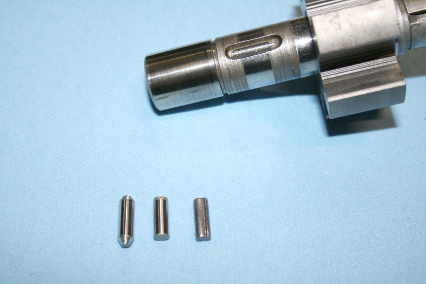 I decided to throw caution to the wind, take the day off and do the whole rebuild in order to get the car back on the road for the show this weekend. So much for lofty plans, at least I got the pump done. I went over to Napa, and they told me they dont carry any solid dowel pins. They recommended Ace Hardware, and sure enough they had a large selection of them. I bought two, one 3/16 x 1/2 and one 3/16 x 3/4. 3/16 x 1/2 skw : 08236 73720 label : 44240-F price : .30
|
3/16 x 3/4 skw : 08236 73722 label : 44241-G price : .35 The 1/2 long dowel pin was the same length as the orginal one, but I wanted to fill the groove, so I bought the 3/4 also to grind down to get a more snug fit. |
|
 Then I pounded in the seal, this is the one that came in the kit. I have always used a hammer, and tapped back and forth, side to side, in a star pattern, and circular to get the seal to go in straight. |
 |
|
 Then I used a 15/16 socket to drive it in until it stopped moving. |
 Next was to disassemble the pin assembly, removing the gear and split retainer ring. |
|
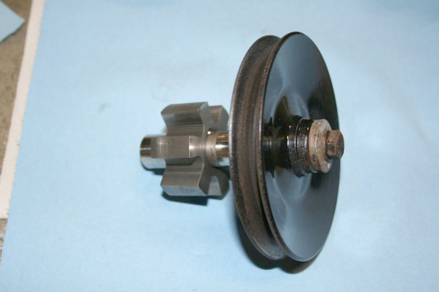
 Assemble the pulley onto the pin, it helps to stick the dowel pin in the groove and temporarily put the gear back on |
|
|
| Slide the gear back off, and put some lube on the pin and seal. | 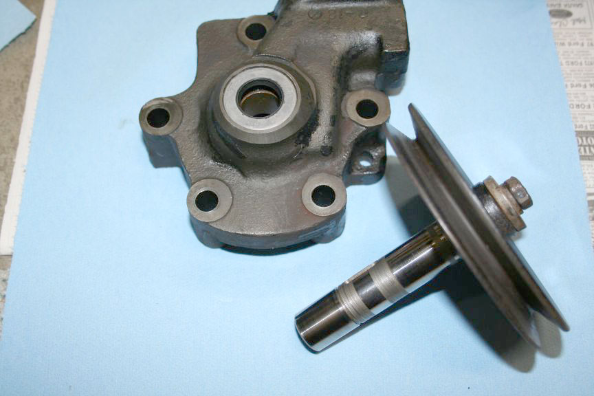
|
|
 Slide the pin into the seal and through the housing half. |
|
|
| Set the housing half onto the pulley and gather these parts. | 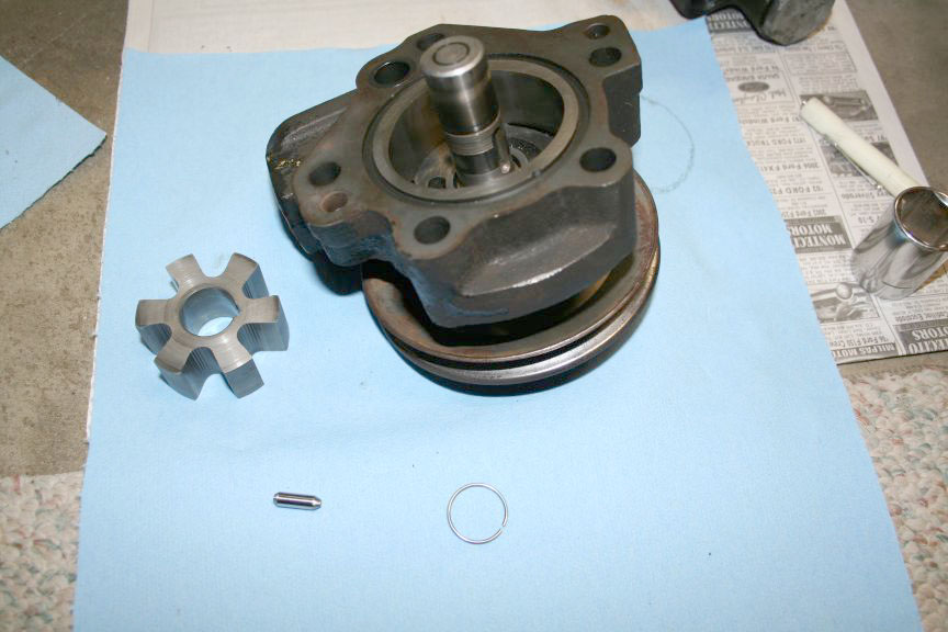
|
|
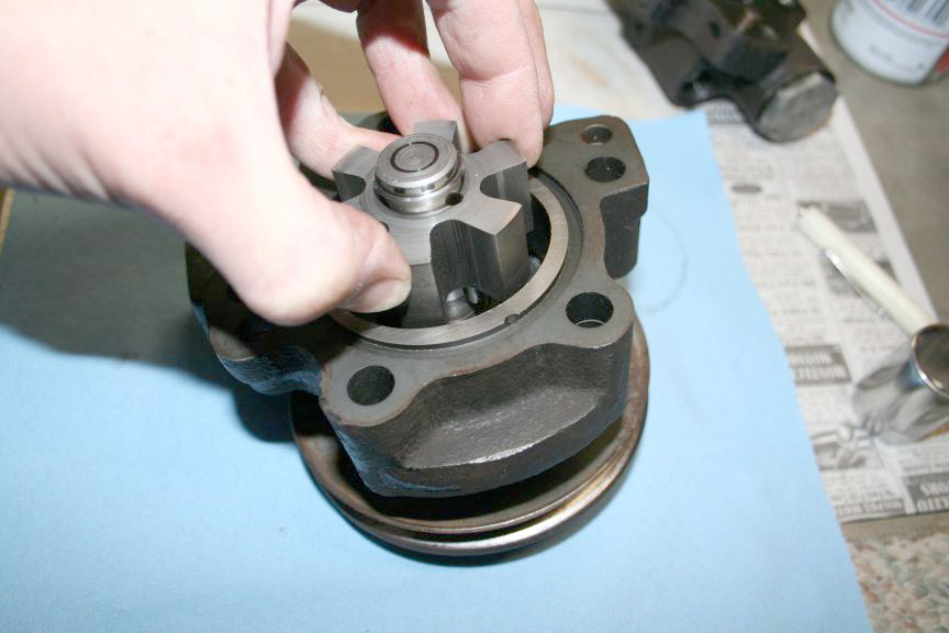 Then assemble them, making sure to match the direction of the "teeth" on the gear. It IS directional, so dont put it in backward! Now put the split retainer ring into the groove. I should note that the ring was worn flat on one side from being next to the gear for 40 years. I put the ring back on reversed to put off buying a replacement for yet another 40 years. You can see the 'flat' facing out in the picture. |
|
|
|
|
|
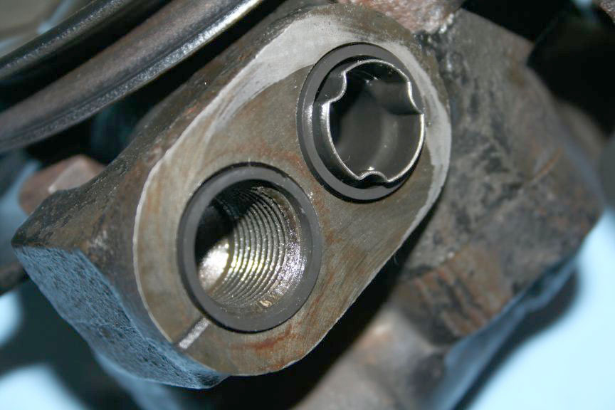
 Gather up these parts, two orings and the cylinders. Remove the old smaller o-ring if its still there. |
 Here is where they go. |
|
 I used some fine sandpaper, and with some lube spread on the opposite housing half, cleaned up the surface to insure a good seal. |
 Put some lube on the o-rings. |
|
 Align the housing dowel pins and tap the assembly together. |
|
|
 Gather up your bolts, brackets and remove the pulley by holding the pulley and loosening the pulley retaining bolt. |
 Assemble the brackets and bolts to the housing and snug the bolts down following a "star" pattern. |
|
 I grabbed the thin bracket in my vice and torqued the bolts to the required 20-25 foot pounds. |
 And put the pulley back on. |
|
 Remove the two old reservoir seals. |
 Gather these parts up. |
|
 Put the new seals in, and apply lube. |
||
 Put the bolt in with the reinforcement plate as shown. |
| |
 Back in the vice and torque to 30-35 foot pounds. |
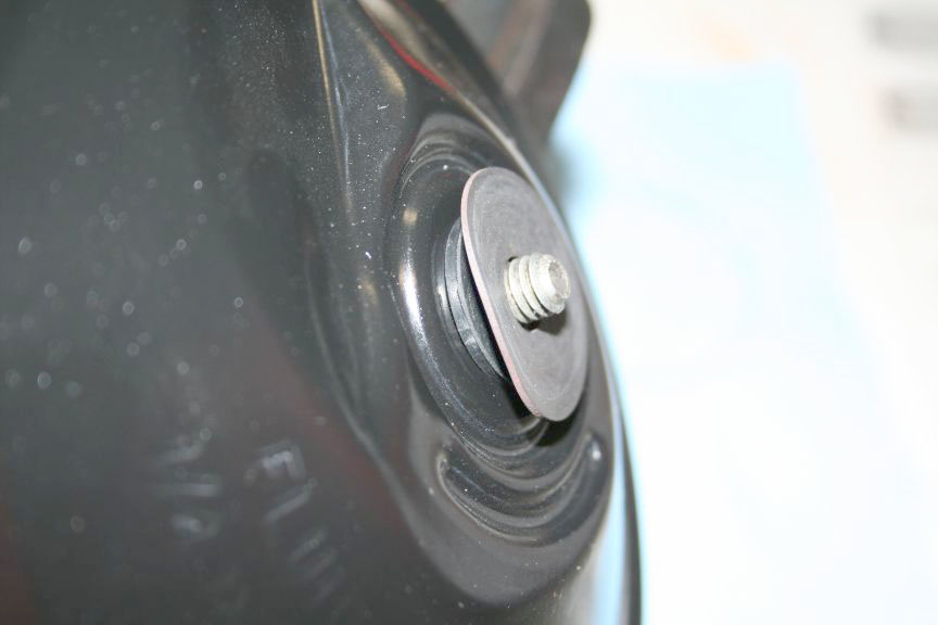
 Install the rod with threads at either end, torque 40-60 inch pounds. |
|
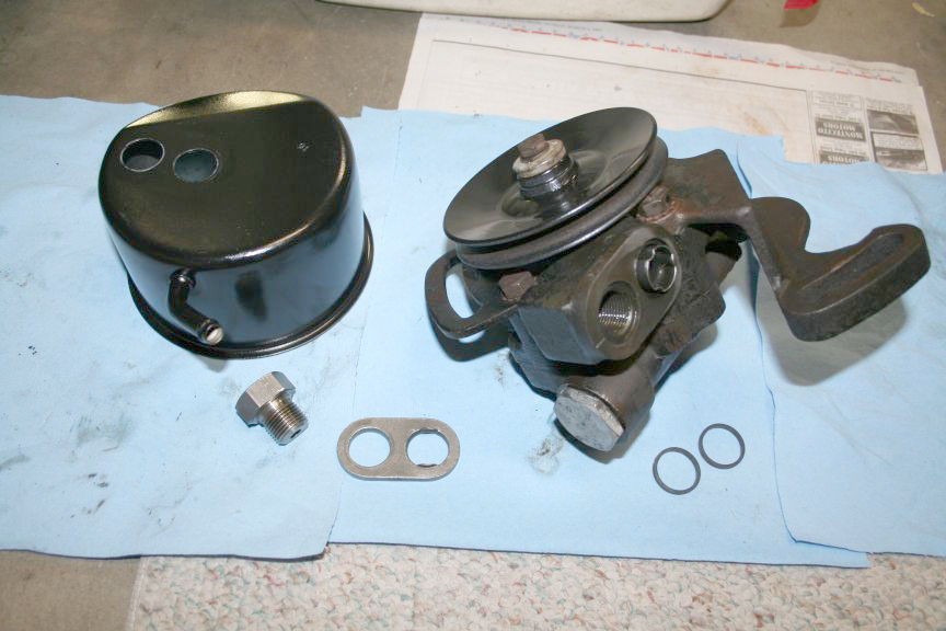
 Gather these seals and the lid. |
||
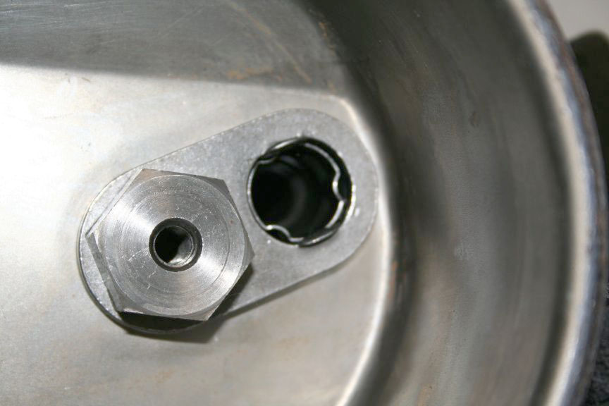
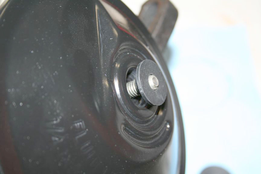 Put the large seal into the lid, and install, put the small seal with the bump into first. |
 Then add the large flat skinny one. |
|
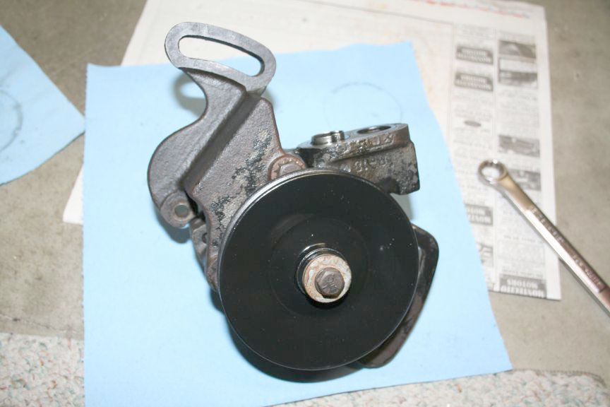
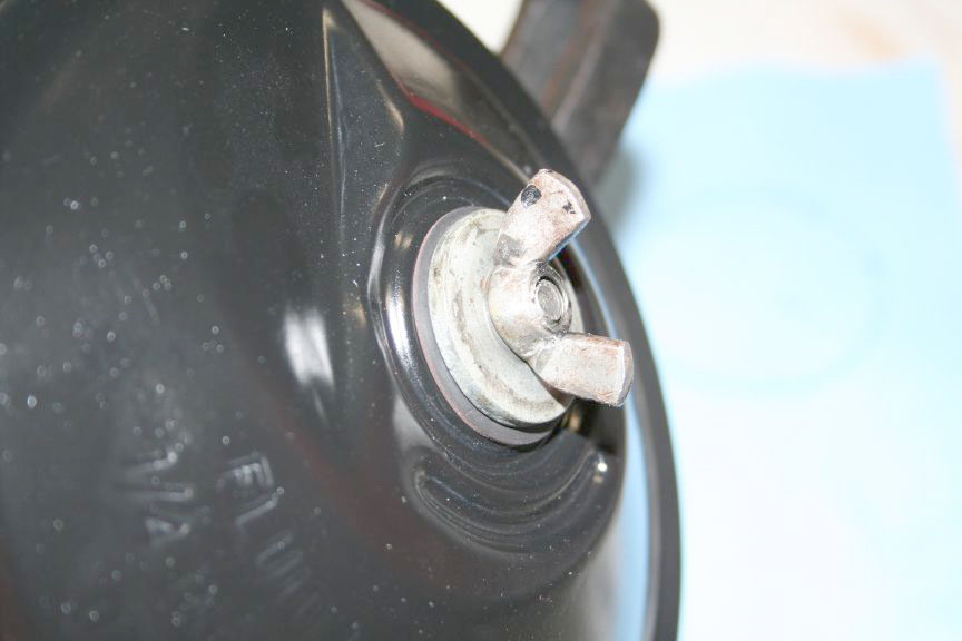 Big washer and wingnut and your done! |
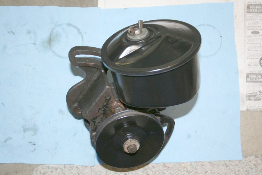 Here is the finished pump. I wish I didnt have the ram, control valve and all the hoses left to do still. |
|
|
![]()
Some technical opinions are my own from experience, other informational data is from online sources with credits when available and while care has been taken to be as accurate as possible, it is offered only as a guide and caution should be exercised in the application of it.