| Author |
 Topic Topic  |
|
|
sbca96
Commander Member

USA
2627 Posts |
 Posted - 09/21/2006 : 04:38:48 AM Posted - 09/21/2006 : 04:38:48 AM


|
Updating picture locations so I can show my dad all that I do here.
You guys are supposed to message me when you find the red x's.
Here is the disassembly proceedure for the R1 fuel pump, I will add
text where it will be helpful, but the pictures should be sufficent.
The stock Studebaker fuel pump is similar, so most of this will apply
to that unit as well. If you have dialup, this might be a little bit
for you, hit the red X or the "Stop" button on your browser. If you
want to see a certain picture, right click it, and hit "show". I am
using a rebuild kit from Studebaker International, with a different
stem seal that is included in the "Cellar" kit :
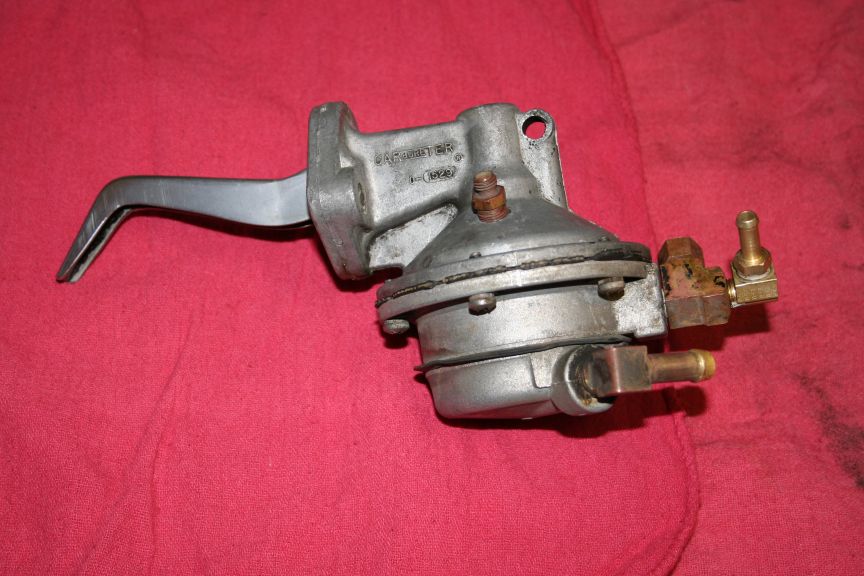
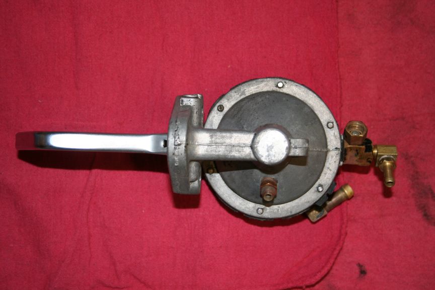
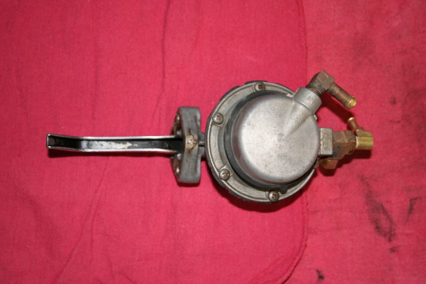
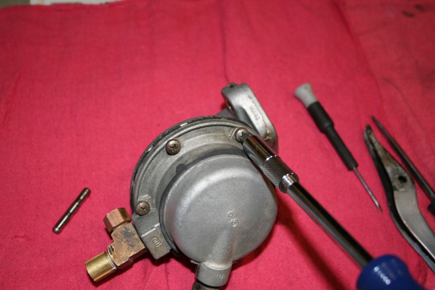
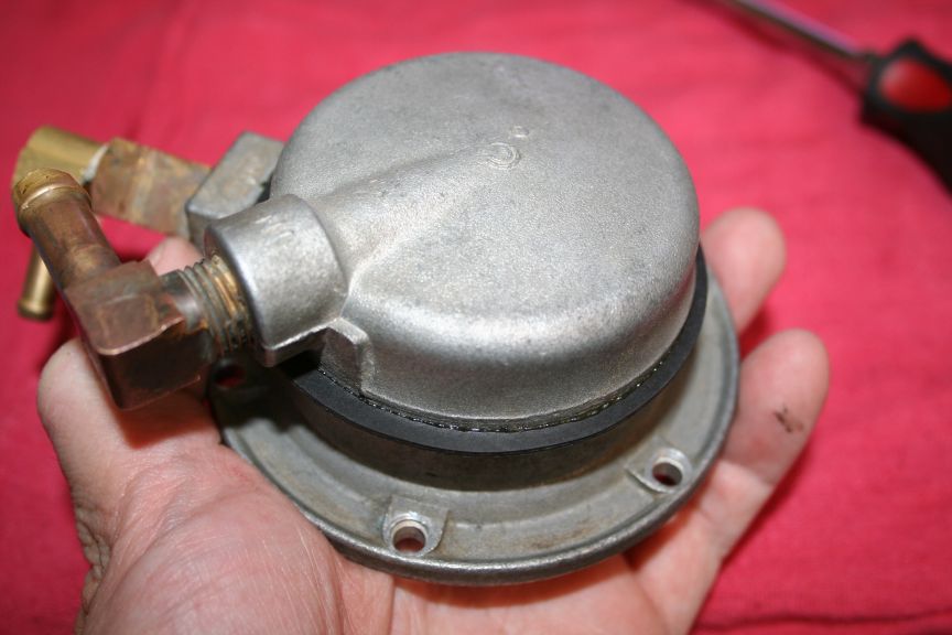
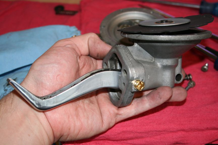
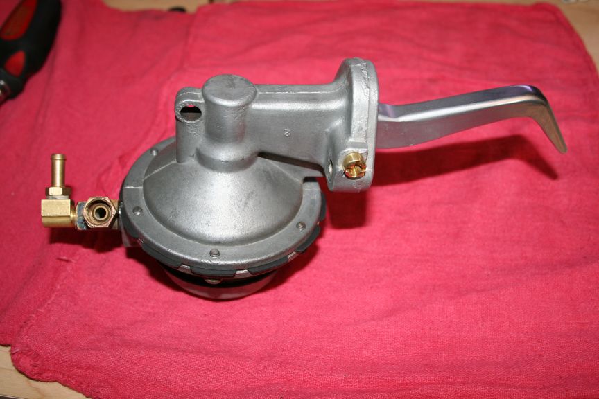
Here is the pump, off the car, and cleaned :
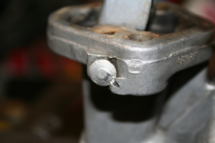
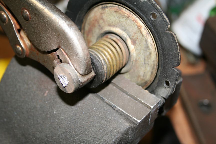
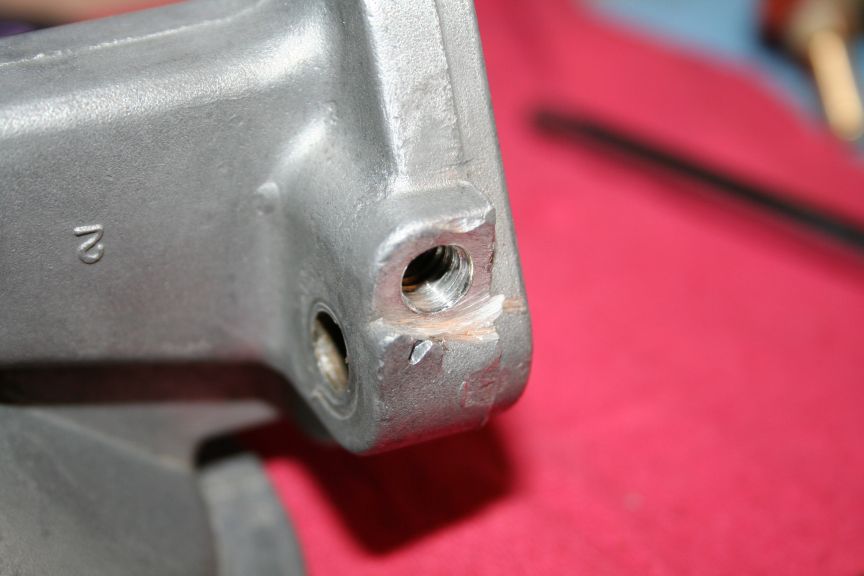
Closeup of the plug holding the pivot pin in :
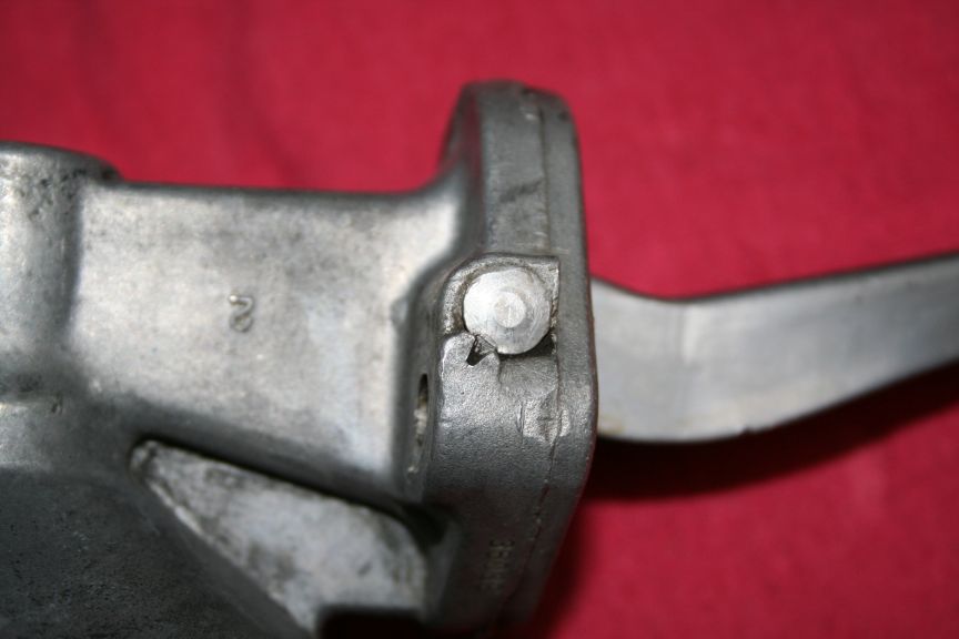
Put in a vice (carefully) pinched on the "nose", and the plug hit with
a center punch a few times to make a ridge. The material is pretty
soft, I found that a screwdriver would "grind" it away :
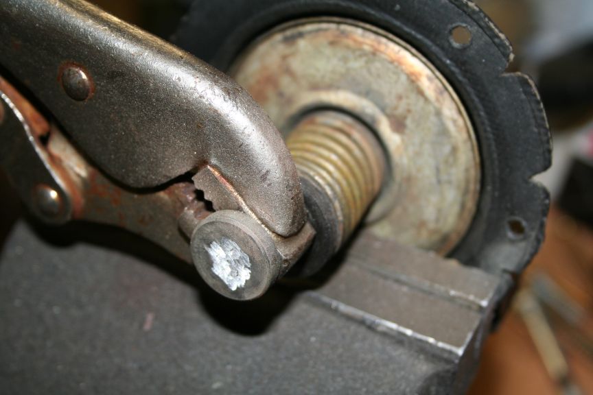
I used a flat blade screwdriver and tapped around the edge, creating a
bump to pry against :
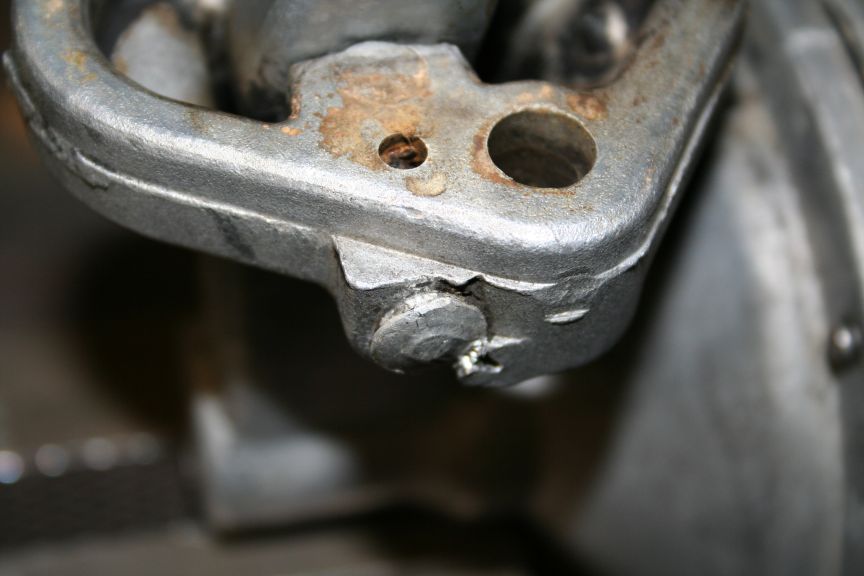
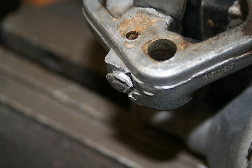
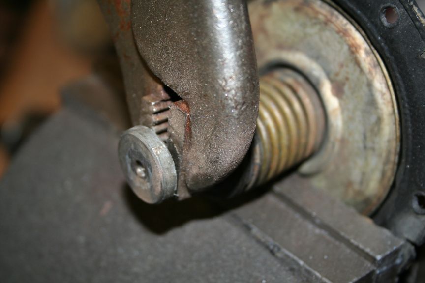
Again with the flat blade, I chiseled (by hand) material away to gain
better access to the plug, and get it out from under the "stake" :
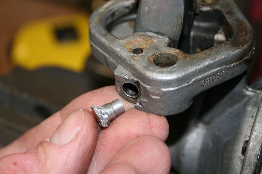
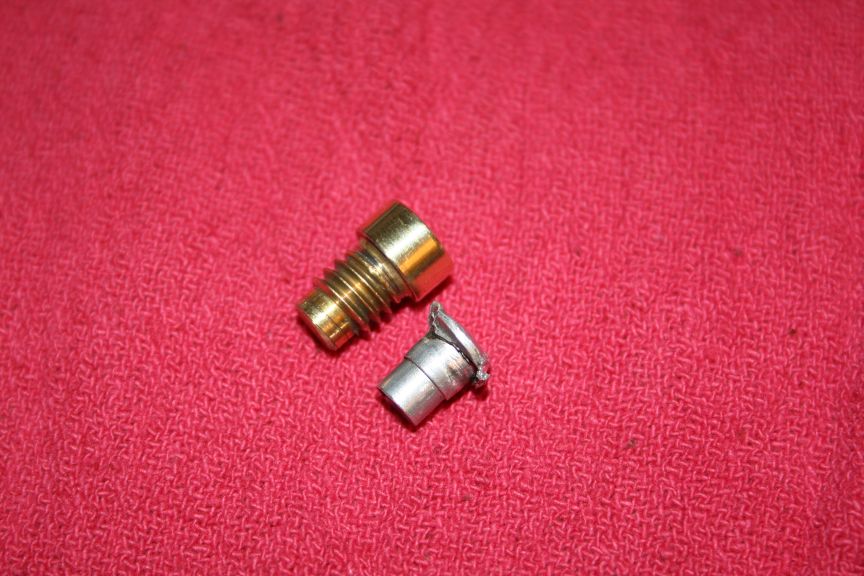
Plug popped out. The plug has a MUCH longer tip on it, the one in the
kit is very stubby, and will allow the pin to move back & forth more.
I think I will tap the hole and modify a screw to plug the hole :
Pin comes out with a little cleaning of the hole :
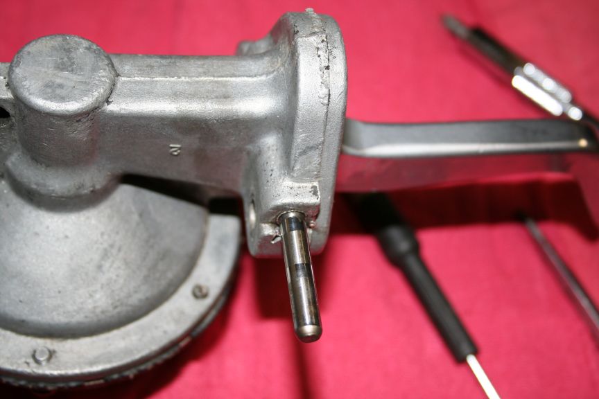
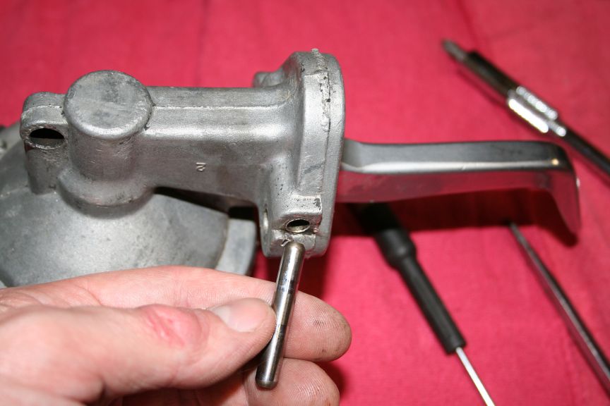
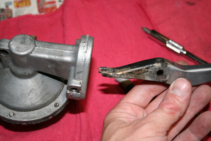
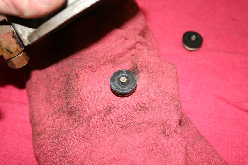
Once the pin is out, the arm comes off :
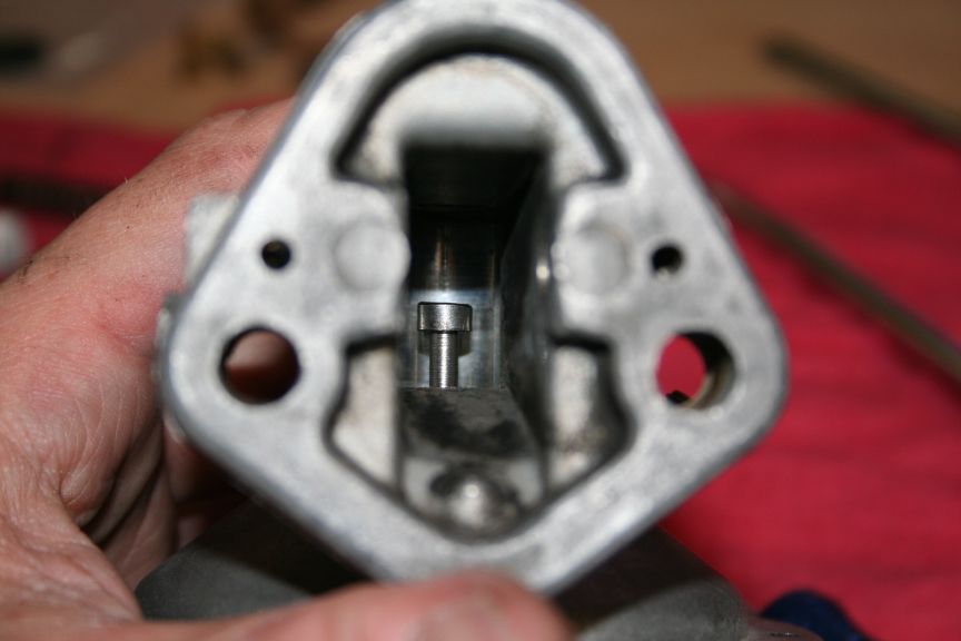
Down inside the housing :
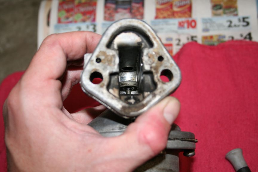
Remove the screws from the bottom :
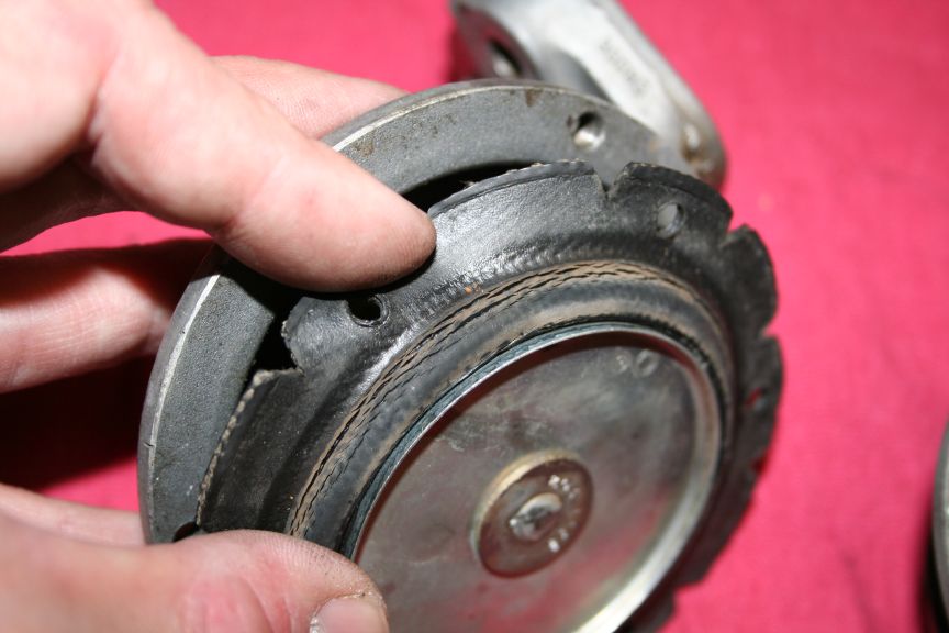
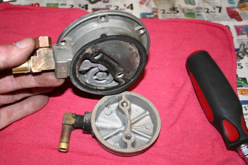
Crack it open :
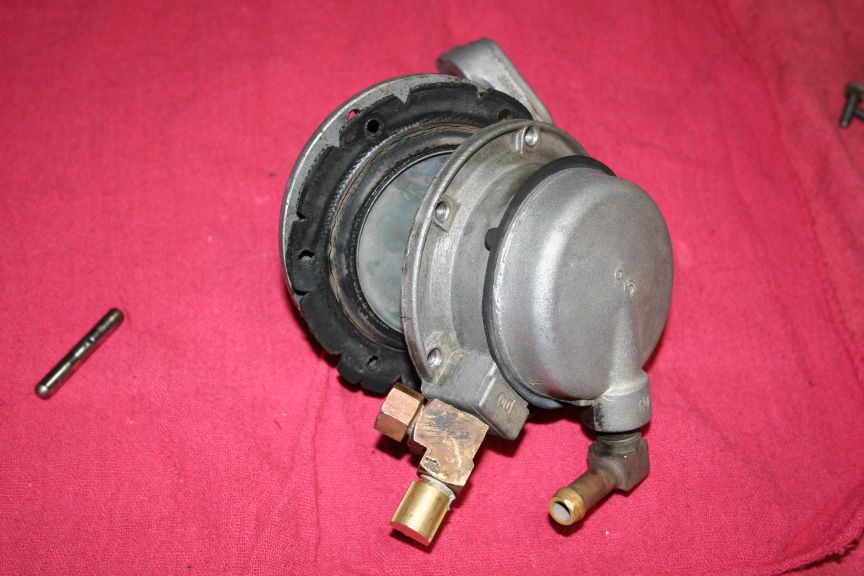
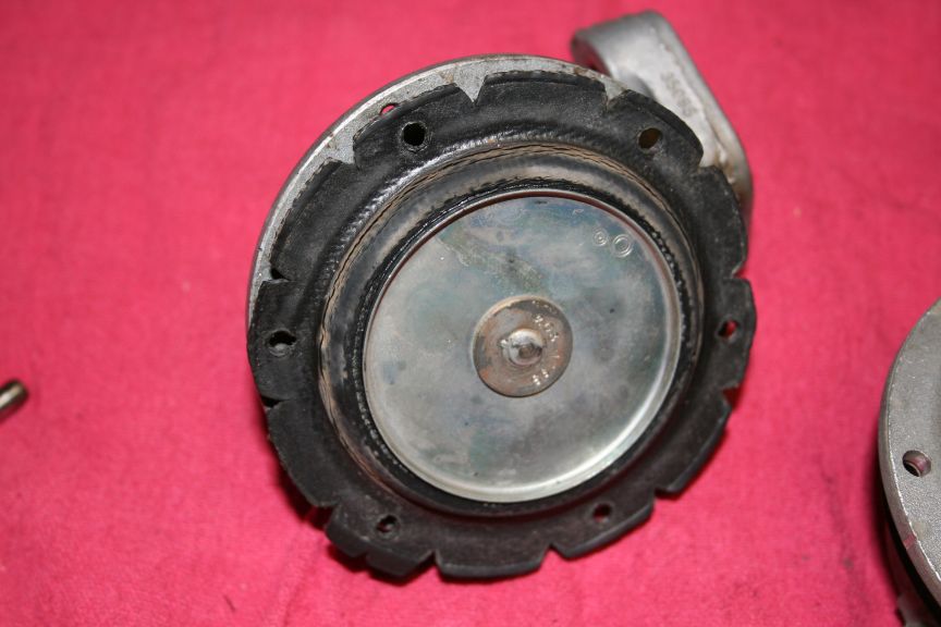
Was happy to find the diaphram cracked (needs replacement) :
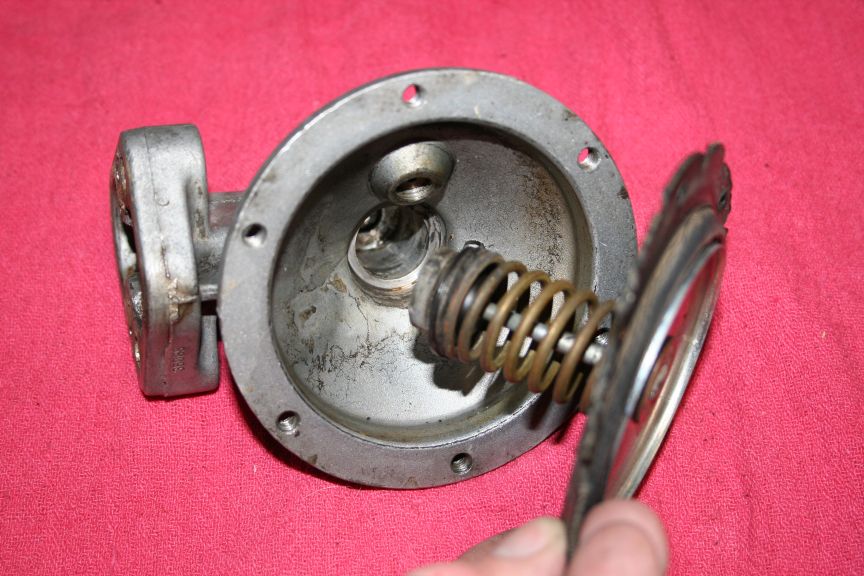
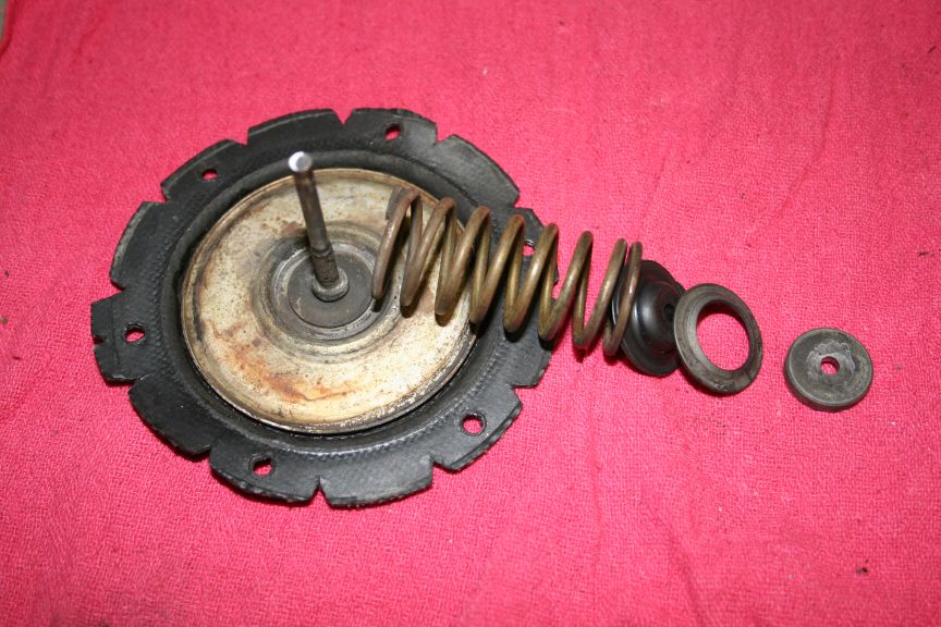
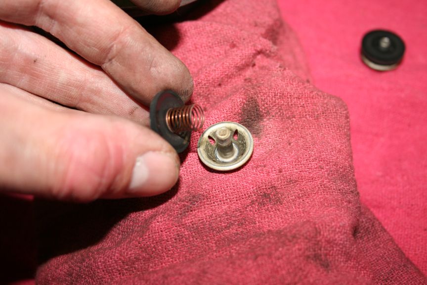
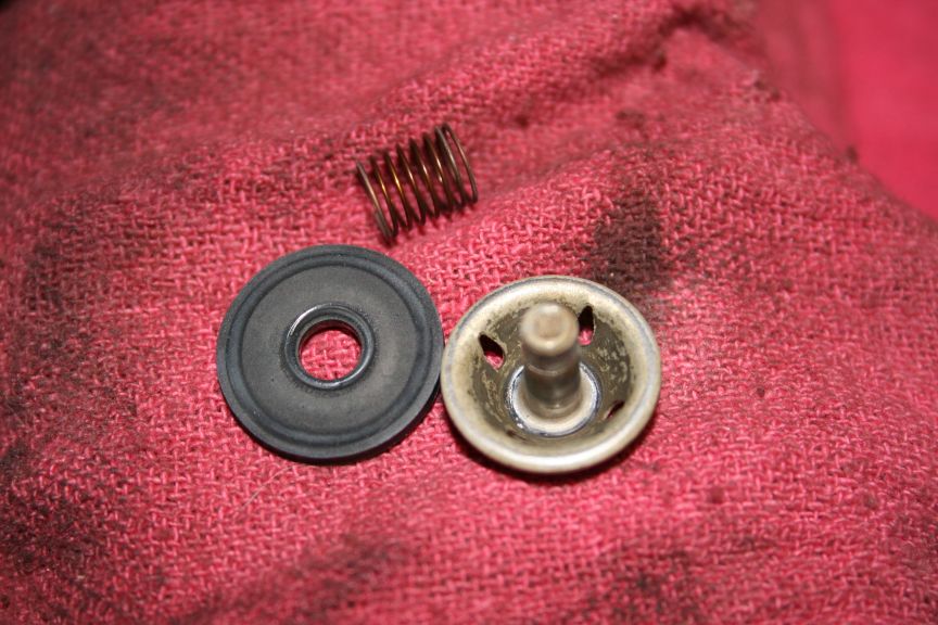
Assembly slides out :
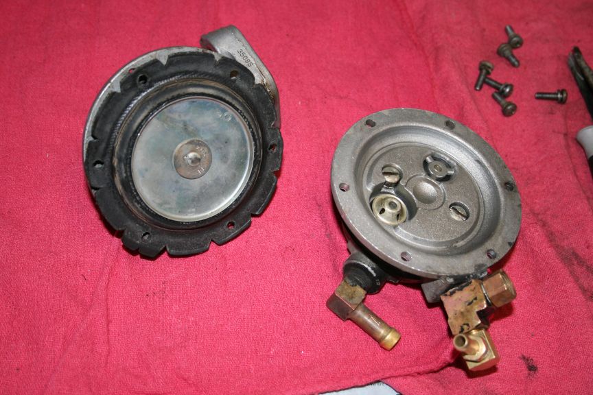
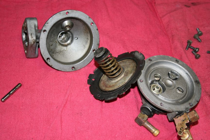
Apart :
New diaphram to old diaphram :
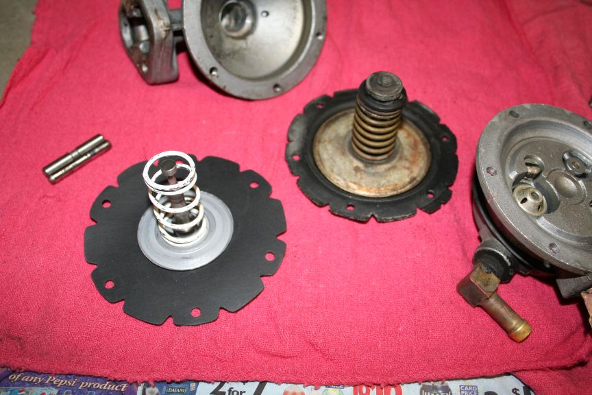
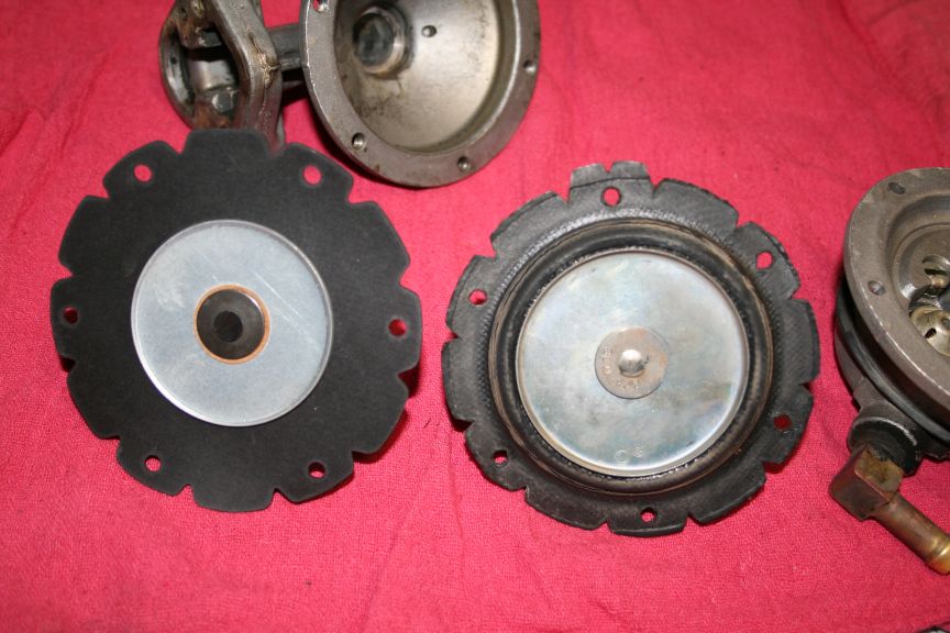
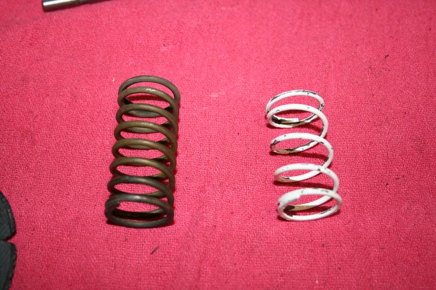
New spring / old spring :
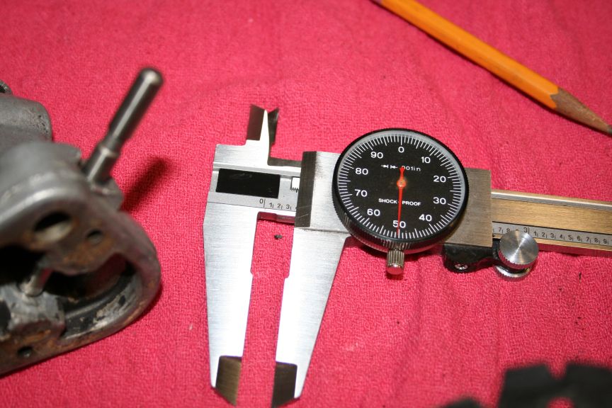
Looks like the distance from the surface of the plug hole, to the pin
is about .350. Thats plenty to tap for a screw. Then I can remove
some of the threads from the screw to clear past where I dont tap, &
make it as long as the original plug tip was.
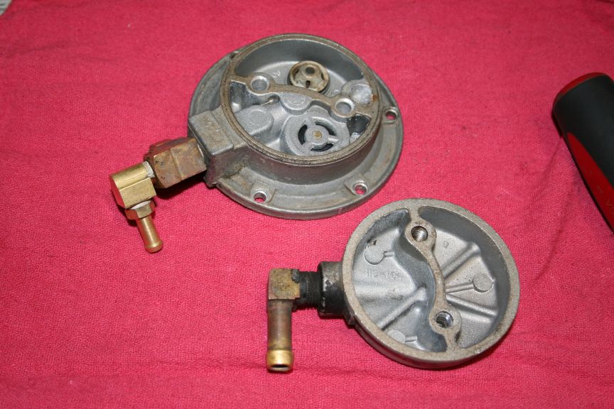
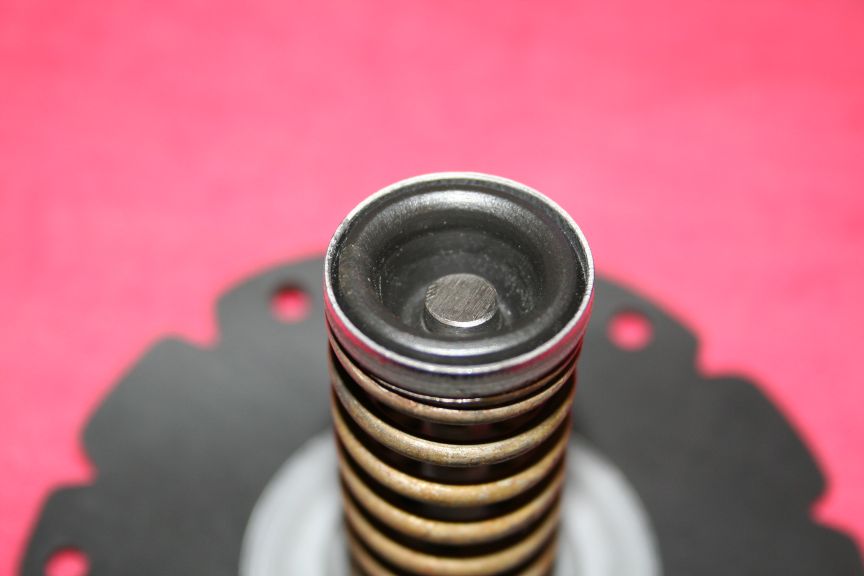
Inside the upper housing :
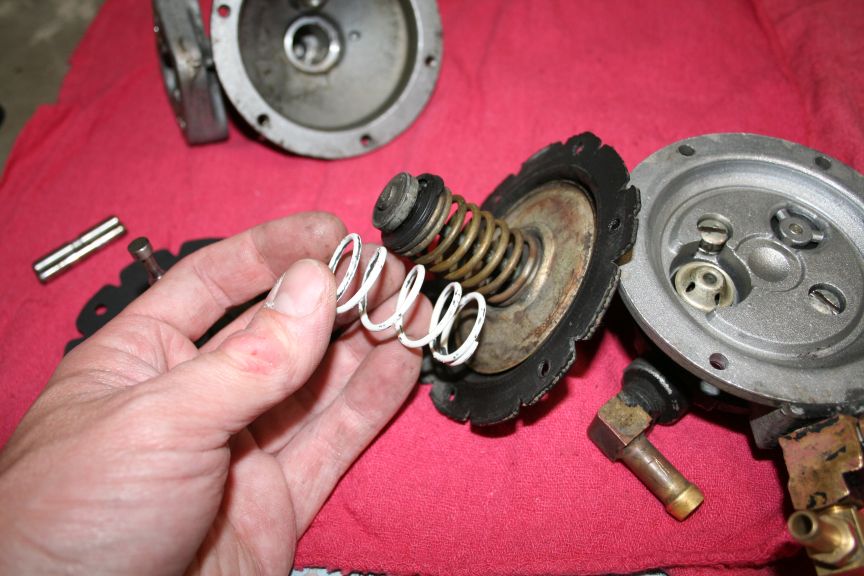
Decided I wanted the higher fuel pressure of the original spring :
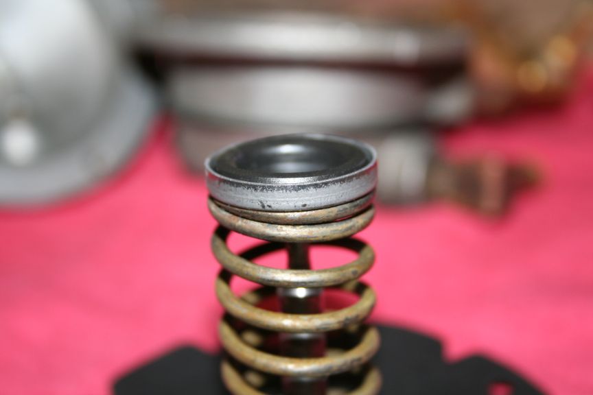
Disassembled :
Old spring / new spring :
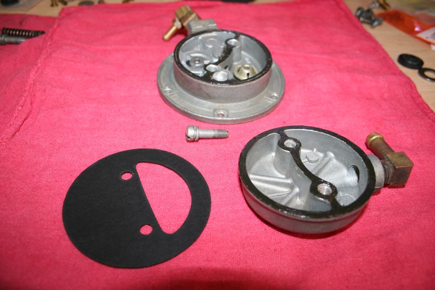
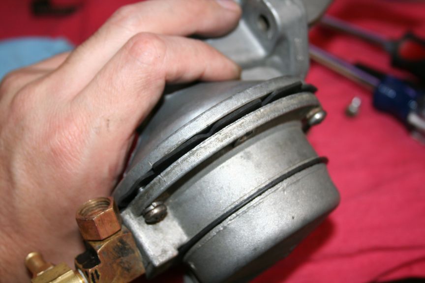
Remove fuel bowl screws :
Crack it apart :
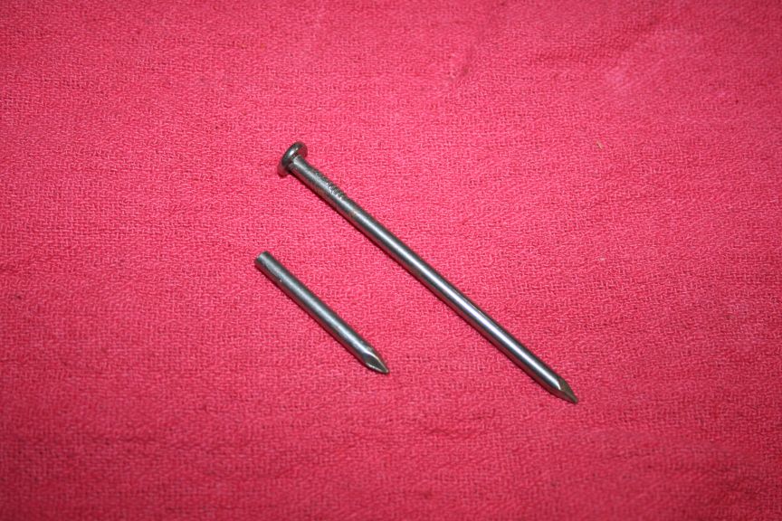
Cut off the end of a nail, the head side might work easier :
Clamp in your vice grips :
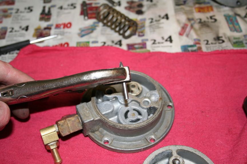
Center over the valves :
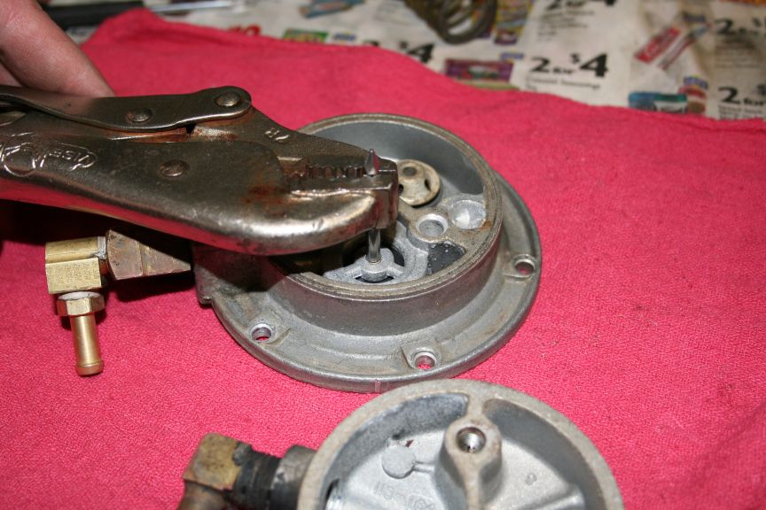
Gently tap them out - doesnt take much :
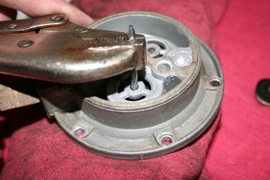
Old valve assembly :
Tom |
Edited by - sbca96 on 07/17/2009 01:37:36 AM |
|
|
sbca96
Commander Member
USA
2627 Posts |
Posted - 09/21/2006 : 04:39:43 AM
|
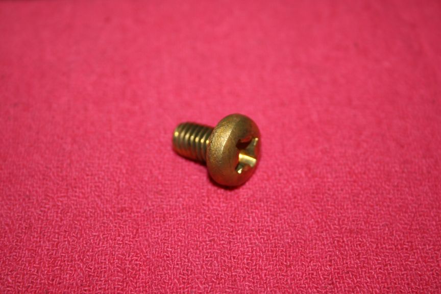
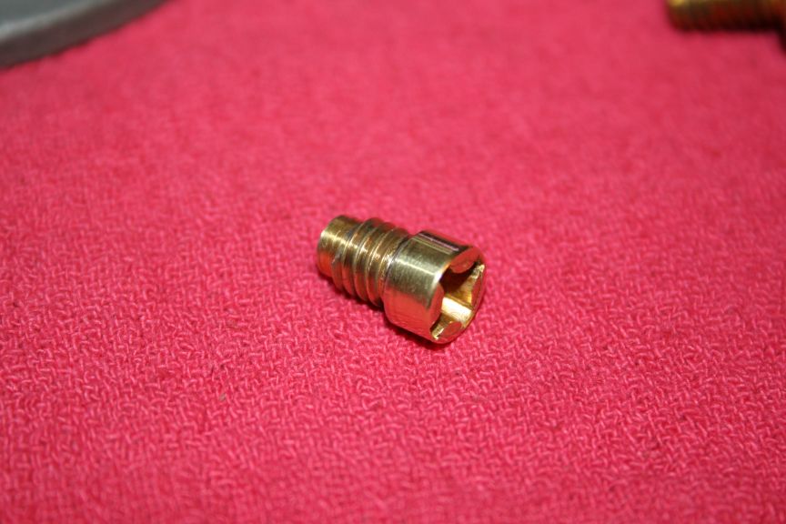
Modifications : I decided to go through with the tapping of the plug
hole and creation of a filler screw, I started with a brass 5/16 pan
head screw 1/2 inch long :
Turns out the pin is .250 diameter and the minor diameter of a 5/16
tap is .257, since its aluminum - you dont have to enlarge it. I ran
the tap down approx. .250 inch :
Here is the screw, turned the head down to .380 diameter, removed all
but the first .250 of thread, shortened to leave some pin movement :
Cleaned up the seat with the dremel and a file :
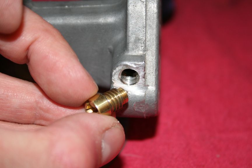
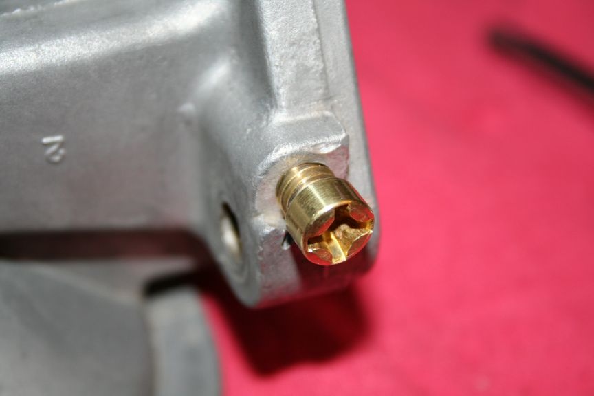
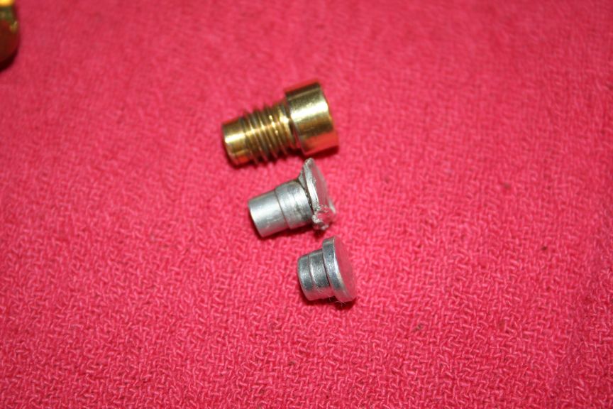
Comparison between new theaded plug and original soft plug :
Comparison to the stumpy plug supplied with the S.I. kit :
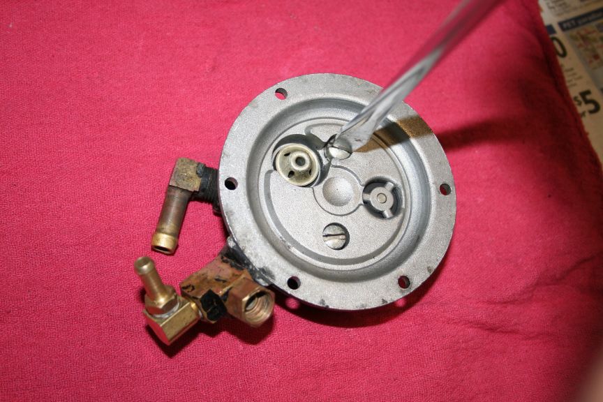
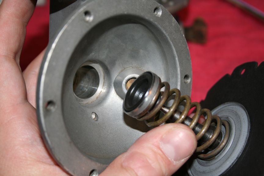
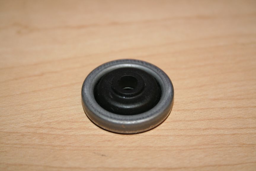
Proper installation of the stem seal :
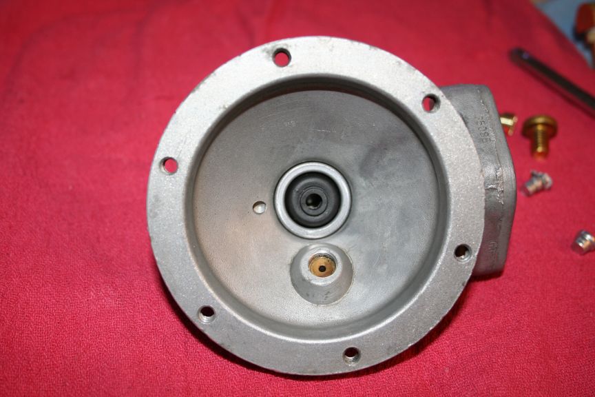
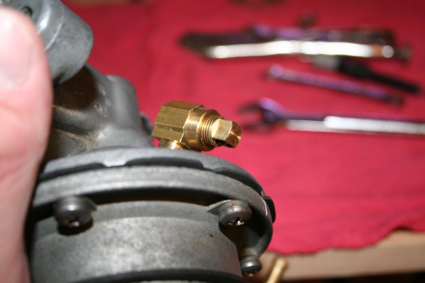
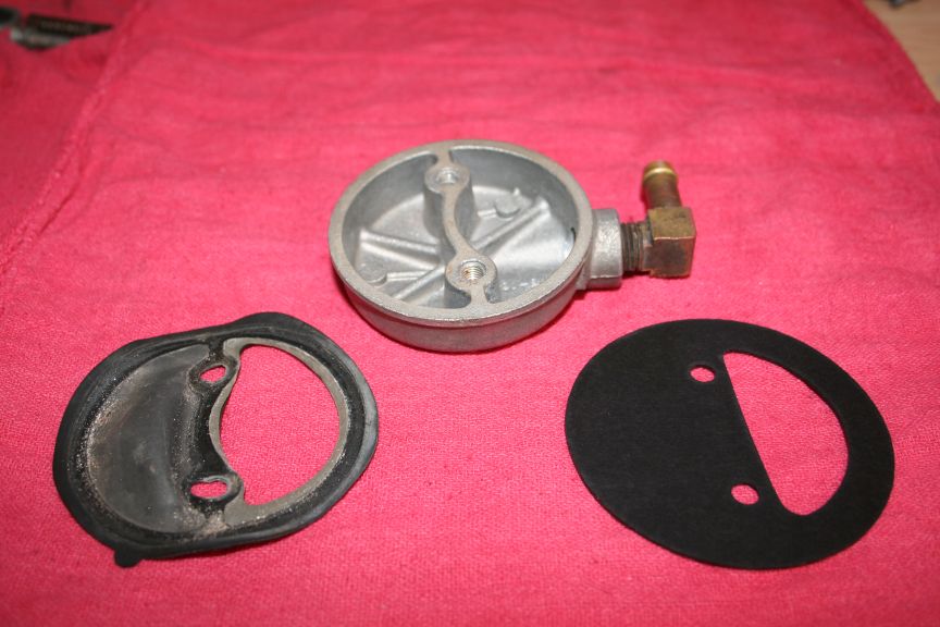
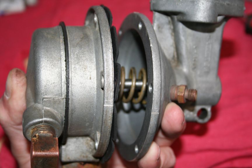
My fuel pump is actually an R2 pump, which is why it has that boss for
a 1/8 pipe fitting. The R1 has roughly a 3/16 diameter vent hole. I
didnt want to drill the housing, so I decided to make a vent that wont
allow water or dirt to get in (that easily). This is what I did :
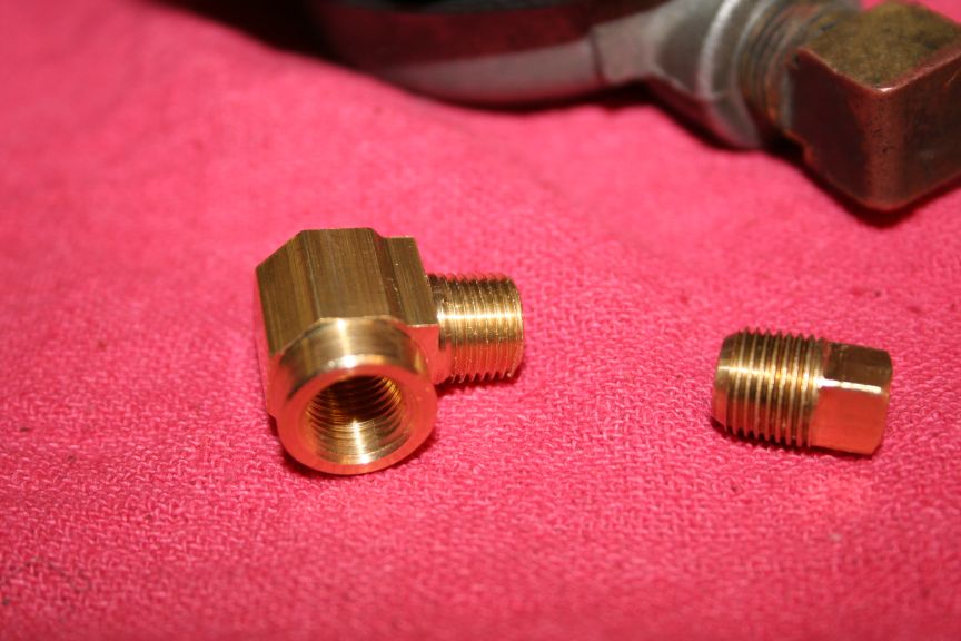
1/8 male NPT to 1/8 female NPT 90 degree fitting from Home Depot, and
a square 1/8 NPT pipe plug :
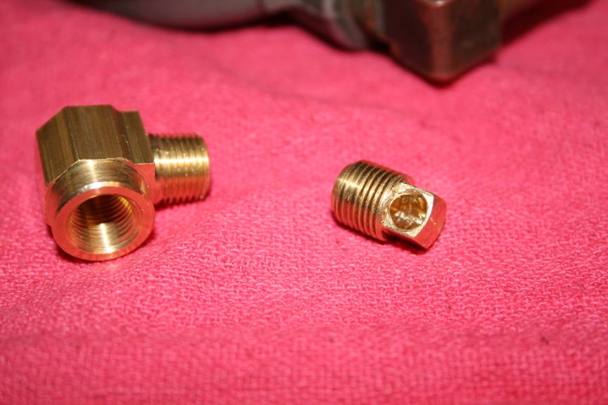
Drilled the hole deeper in the plug, and screwed the pipe plug into
the 90 degree angle fitting to find out which "flat" faced down to
drill a hole to the center hole :
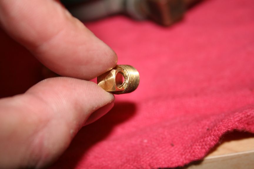
Hole goes through :
90 degree angle screwed into the housing :
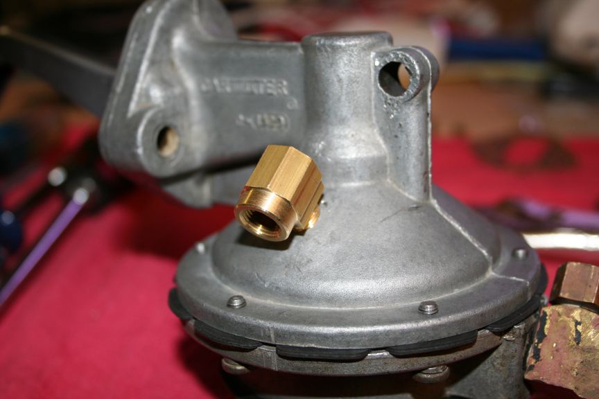
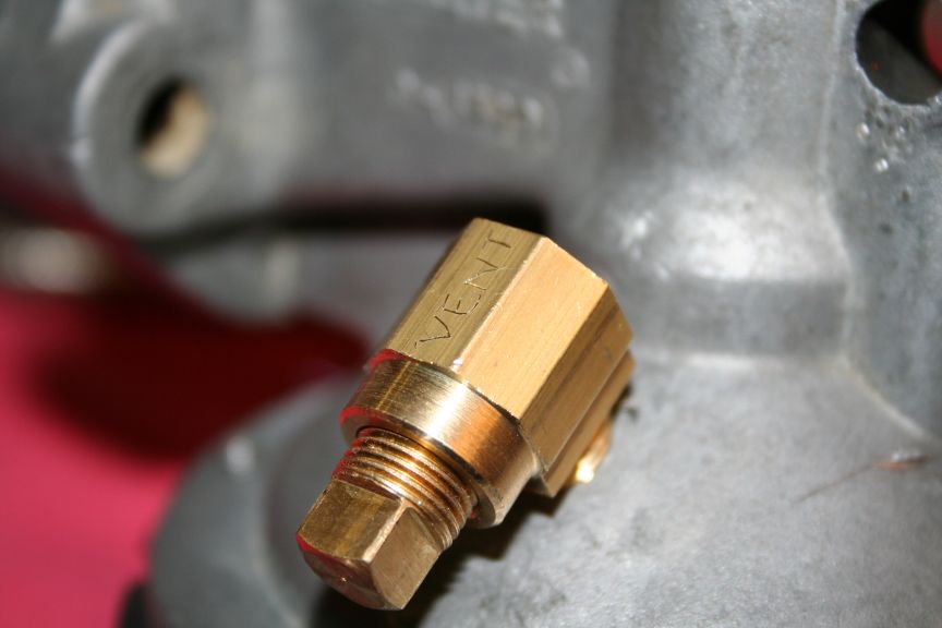
Plug (which 3/16 through hole) screwed in - you can see the hole is
facing down and in.
Decided to label it for the next owner :
Tom |
Edited by - sbca96 on 07/17/2009 01:43:16 AM |
 |
|
|
sbca96
Commander Member
USA
2627 Posts |
Posted - 09/21/2006 : 04:40:25 AM
|
I could just be like a Chiltons manual, and say "installation is the
reverse of removal" - but how often is that REALLY true??
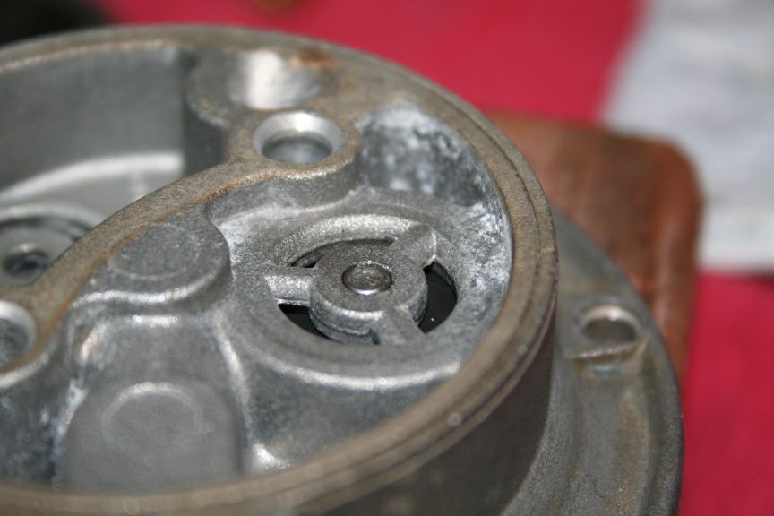
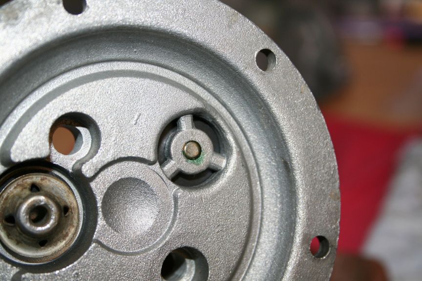
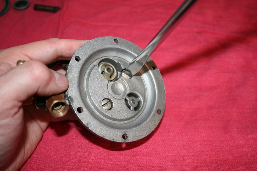
Here is the correct way the valve goes together. I had to look at my
OWN picture above to make sure I had done it right!
The mushroom shaped deal gets pounded in until its flush with the top
of the hole (or bottom), you CAN go too far - so dont!
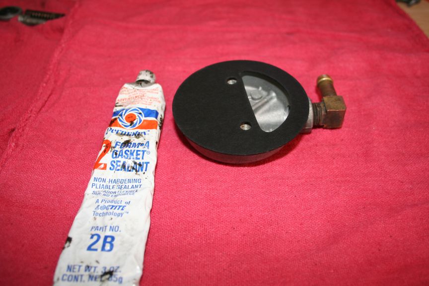
I used Loctite in the hole, just a little bit. You dont need much :
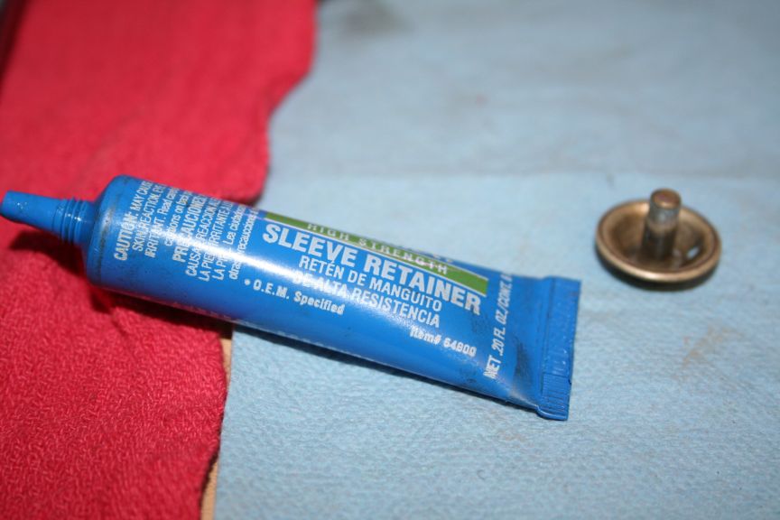
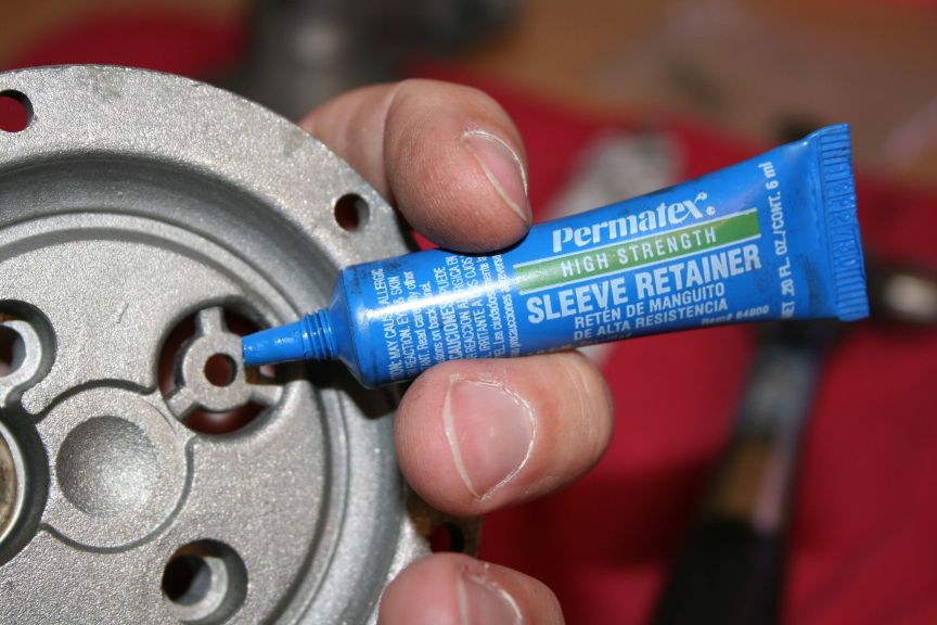
Wipe off the excess :
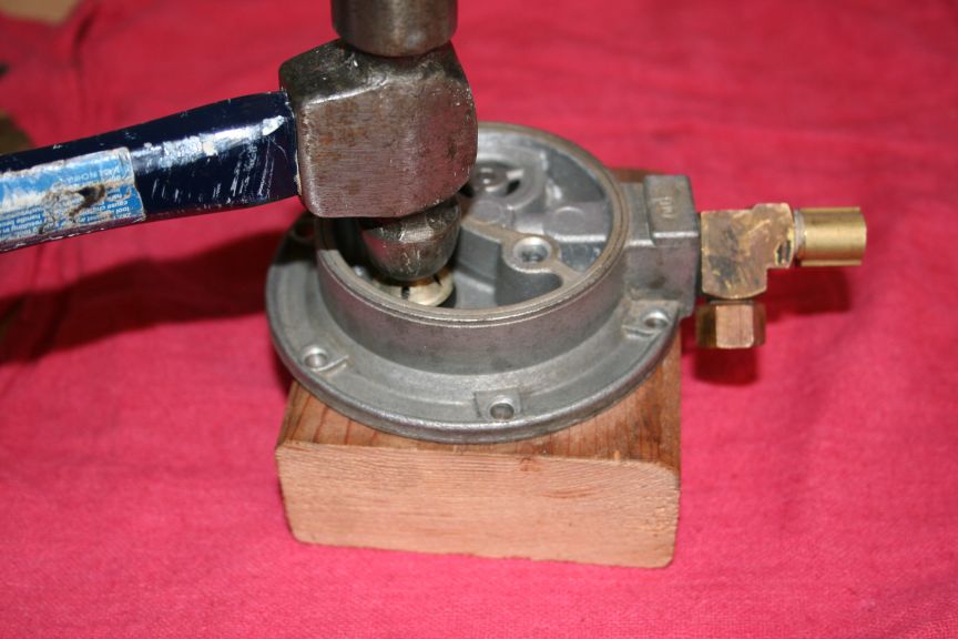
Hammer it in. I used a wood block, that way I didnt harm my table, or
have to remove the fittings I just redid :
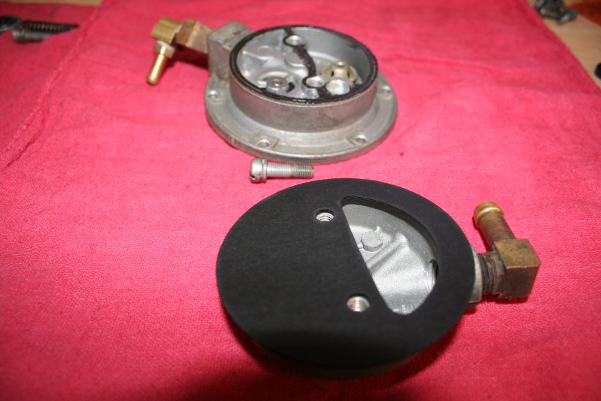
Make sure you put this gasket on correctly. If you do it right, you
can blow through the assembly, if you put it on 180 degrees, then you
will "seal" the input, and no gas will get through. Thats bad.
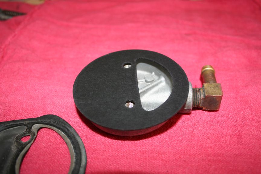
I used a VERY light film of permatex on both sides of the gasket, I am
paraniod about fuel leaks. After looking at the way the diaphram goes
together, I realized that I COULDNT use permatex there. If you cant
use it both spots, its pointless to use it at all. If I had to do it
over, I would NOT have used the permatex on the fuel bowl :
Then tighten the screws, I read that one thing to do to insure that it
doesnt leak after, you take the parts and use sandpaper or emery paper
and place it on a glass surface, then run the part back & forth until
you get a smooth uniform shiny part. I didnt want to do that since it
has a nice rough texture to the sealing surface, which seemed like it
would seal better then a smooth surface. Food for thought.
You can see what oozed out - even though I used a little bit!
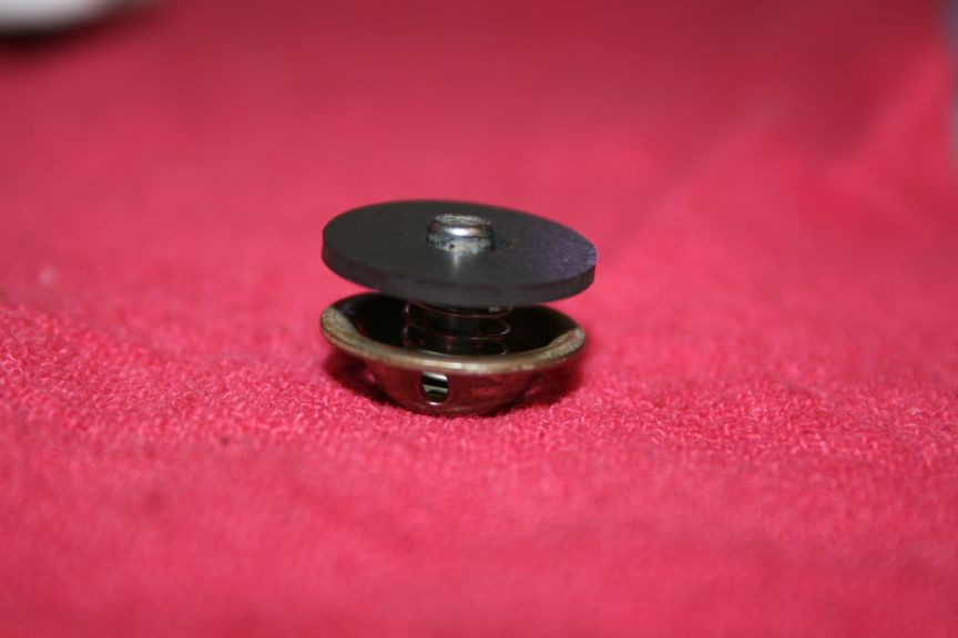
Here is the stem seal installed on the old higher pressure spring :
Fits into the housing :
This picture is deceiving, I first thought it would go together better
if I did it this way, but the instructions say to put the arm on first.
They are right, if you push the top of the shaft through the housing
and then stick the "fork" end under the "head" of the shaft, it will
hold it all together while you put the screws in. Nice.
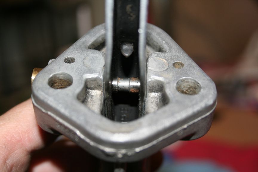
"Head" on the shaft :
"Fork" under the head :
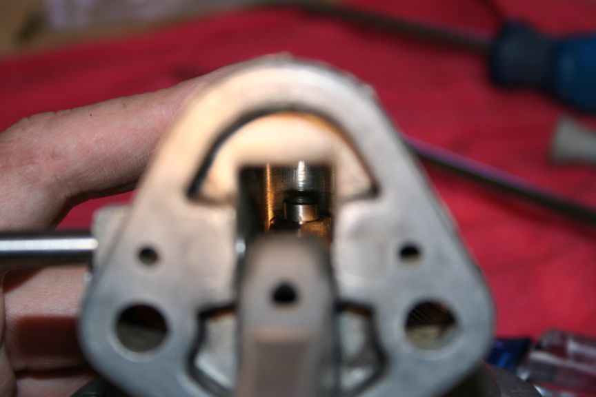
Pin into the hole, through the arm :
This is what concerned me about the "short" push plug. Though I didnt
measure it, it LOOKED like the short plug might allow the pin to move
over far enough to leave one side of the arm with no support & riding
in that necked down area in the center of the pin. Thats why I liked
the old longer nose pin better, and made my screw to match it :
Arm installed, pin in, screw set, holding diaphram :
Putting the screws in .. do NOT tighten them as you install them! Just
leave them loose for now.
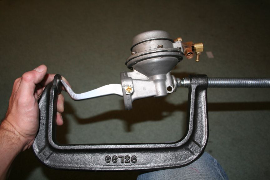
Here is the FUN part. Page 5 in the "Avanti Workshop Manual" in the
Studebaker shop manual, clearly states on step 7 :
Align the indentification file marks and install the
valve body-to-pump body attaching screws loosely.
Hold the cam lever in its maximum stroke position,
then tighten the attaching screws securely.
Oh Yah right! I need at LEAST two more hands to do that. I tried a
few different things, and none worked. My vice doesnt open wide enough
and tightening the assembly in an 8 inch C-clamp didnt work either. It
would pop right out. I figured out that if I marked the arm, and did
a few adjustments for fit, I could push the pump INTO the C-clamp with
the result being the arm at full stroke. Takes a few trys, I was able
to tighten the screws pretty well, then it popped out, I finished it
out of the clamp, but I think it was tight enough it didnt move back :
Time to put that spring back on the arm. I put the end into the arm
first, and pryed it onto the bump in the housing :

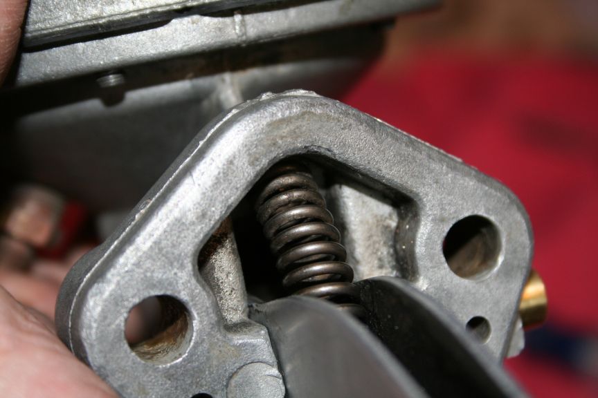
All done .. ready to go back on the car :
Tom |
Edited by - sbca96 on 07/17/2009 01:50:13 AM |
|
|
|
N8N
Commander Member
USA
5258 Posts |
Posted - 09/21/2006 : 07:40:54 AM
|
I'm at work, so I can't see your pics :( but just thought of something
worth mentioning - when replacing the check valves, drive the
mushroom-shaped metal bits in only far enough so that they are flush on
the other side. I remember disassembling a "freshly rebuilt" R1/R2 pump
once that wouldn't pump, only to find that the check valves were driven
in all the way!
Also, you forgot the part about drilling out the
seized screws holding it together, and also the scrubbing all the
caked-on grease off with a toothbrush :/
As a side note, the
screws holding the valve body to the bowl are the same on an R1/R2 pump
as on a standard late V-8 pump. This is a Good Thing as I had to drill
one out, and was unable to find a suitable replacement, even at the
local fastener supply place that generally has everything.
nate
--
55 Commander Starlight
https://home.comcast.net/~njnagel |
|
|
|
sbca96
Commander Member
USA
2627 Posts |
Posted - 09/21/2006 : 11:23:09 AM
|
Luckily this pump "seemed" to have been rebuilt already, though the
kit used must have been a factory type. The housings were already
marked according to the shop manual - with a file. The screws inside
had the wear you would expect from someone trying to break them loose
with a blade not wide enough. It came apart rather easy. I bought a
set of stainless "allen" head screws from Home Depot which I got so I
would have them on hand IF I needed to replace one. Since it all
came apart so easy, I think I will pass on the new screws. I was going
to reuse the stock mushrooms, since they came out without damage. Do
you think it would be worth while to use some "Loctite" on them? I'm
also tempted to use a VERY light film of permatex on the gaskets when
I put it back together. I KNOW that the instructions say they will
seal just fine, but I have NEVER had anything I put together with No.2
leak on me ... and I HATE leaking fuel!!
Tom |
|
|
|
StudeRich
Commander Member
USA
6289 Posts |
Posted - 09/21/2006 : 1:48:21 PM
|
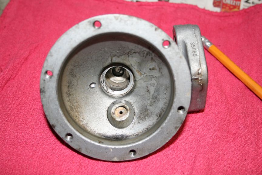
Tom; I noticed something about this 3508S pump that you have, it has
been modified to an R2 by drilling & tapping a hole in the top
cover for a Supercharger pressure equalizer tube. So:
(1) You want to check to see that the vent in top has been securely plugged.
(2)
Be very carefull of that fitting, I wouldn't even think about removing
it, as the cover is weak there, since it has no thick boss to support
it!
I have an original factory equipment used one, that is a 3509S and it is an R1, no boss or hole.
Thanks for the great pictorial of the proceedure, I love it!
StudeRich
Studebakers Northwest
Ferndale, WA |
|
|
|
Mike
Regal Member

392 Posts |
Posted - 09/21/2006 : 2:16:30 PM
|
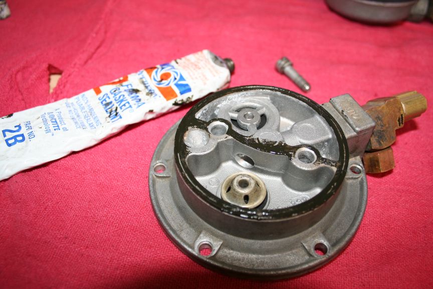
The 3508S pump was made for an R2. It has the housing drilled and
tapped for the boost reference fitting, (1/8", NPT). It looks like the
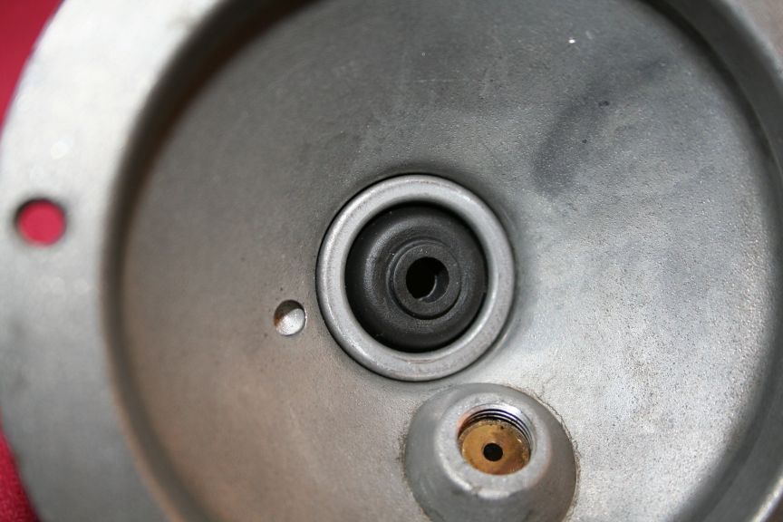
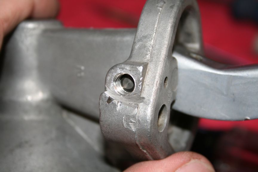
atmospheric vent is cast and partially drilled. You can see the small
hole inside the housing, next to the recess for the spring.
The
3509S pump was made for an R1. I converted one for my R2. The boss for
the boost reference was there, on the inside of the housing. The
Chrysler pump, and others, have the boss too. It's more often on the
outside of the pump. Marine applications require that the vent go to
the engine air filter; and that's why it's there on most pumps. You
don't want gas fumes in the bilges!
I tapped the atmospheric passage; and put a set screw in it from the inside as part of the R1 to R2 conversion.
Mike M. |
|
|
|
sbca96
Commander Member
USA
2627 Posts |
Posted - 09/21/2006 : 2:27:08 PM
|
The fitting threaded into the 1/8 NPT has a .094 hole through it, my
plan was to leave it in, and add a bent tube to it, curving downward.
Is the .094 hole sufficient for the vent? Its been on the car this
way (no tube - just upward facing hole for crap to get in) for as long
as I have had the car. Who knows when the R2 pump was installed.
Also, I assume that the "Cellar" seal is installed with the metal side
against the spring, not the rubber side. The metal is tapered, & so
is the pocket for the spring/seal.
Tom |
Edited by - sbca96 on 07/17/2009 01:39:38 AM |
|
|
|
StudeRich
Commander Member
USA
6289 Posts |
Posted - 09/21/2006 : 4:45:44 PM
|
Thanks Mike for the correction, I've seen so many of those Carters with
the thick boss on the OUTSIDE, that I thought they were the only ones
equipped to properly except the R2 fitting! Now that you mention it, I
see in Tom's excellent Pics, the reinforced hole on the INSIDE of the
housing top ! 
quote:
Originally posted by Mike
The
3508S pump was made for an R2. It has the housing drilled and tapped
for the boost reference fitting, (1/8", NPT). The boss for the boost
reference was there, on the inside of the housing. The Chrysler pump,
and others, have the boss too. It's more often on the outside of the
pump. Mike M.
StudeRich
Studebakers Northwest
Ferndale, WA |
|
|
|
Mike
Regal Member
392 Posts |
Posted - 09/21/2006 : 5:06:57 PM
|
The fitting you have will probably be OK; but stock was a little
bigger. The R1 vent passage is almost 3/16". I plugged mine with a
10-32 set screw. The Chrysler pump's vent is almost 1/4".
The R2
boost reference line is 1/4". The fitting on the pump is a 90 degree
elbow, 1/8" NPT to 1/4" flared pipe. It's "Brass 1/4F 1/8M 90DEG P
9074805" at Advance Auto, for $1.88 .
The spring goes against the
broad surface washer, and compresses the rubber until the edge of the
washer bottoms out in the housing. That limits how much the rubber is
squashed. I think the flat washer lets it get pinched too far.
Mike M. |
|
|
|
sbca96
Commander Member
USA
2627 Posts |
Posted - 09/21/2006 : 5:18:57 PM
|
OK .. so as I show the stem seal in the picture above, is how it sits
in the pocket at the top of the fuel pump. Rubber against the housing
and the steel formed washer against the spring (which makes sense, the
spring would eat the rubber away in no time).
Tom |
|
|
|
Mike
Regal Member
392 Posts |
Posted - 09/21/2006 : 5:27:25 PM
|
Yes!
Mike M. |
|
|
|
N8N
Commander Member
USA
5258 Posts |
Posted - 09/21/2006 : 5:40:56 PM
|
Now that I look at those pics, I need to take another look at the R1
fuel pump for my car. I don't know why it's leaking oil on top of the
diaphragm; I was ASSuming that the stem seal sealed against the *bore*
of the casting, but I now realize it's impossible for that to be the
case. (I didn't disassemble it completely as I didn't feel motivated to
knock the little aluminum plug out.)
Also, my old fuel pump that
I put on that wasn't knocking... it's knocking just as loud as the R1
pump now. I am *this* close to just swapping to an electric pump, but I
really don't have the $$ to buy a good one along with a regulator, nor
the time to set everything up properly. Also I would still like to know
WHY I am having this issue as I will be worried that something inside
the engine is going to fly apart when I least expect it.
nate
--
55 Commander Starlight
https://home.comcast.net/~njnagel |
|
|
|
sbca96
Commander Member
USA
2627 Posts |
Posted - 09/21/2006 : 6:45:14 PM
|
You SURE its the fuel pump?? Have you tried isolating ALL accessories
by removing the belts and starting it? You will be amazed how quiet
a Studebaker becomes. Electric low pressure pumps are pretty cheap.
Maybe its a rocker, a lifter .. or ???
Tom |
|
|
|
N8N
Commander Member
USA
5258 Posts |
Posted - 09/21/2006 : 7:10:12 PM
|
Positive. When I remove the fuel pump and just run the engine on the residual gas in the carb the noise goes away completely.
nate
--
55 Commander Starlight
https://home.comcast.net/~njnagel |
|
|
|
sbca96
Commander Member
USA
2627 Posts |
Posted - 09/22/2006 : 01:40:16 AM
|
Bummer Nate ... dont know what to tell you - updated the "modified"
section above, now that you can the pics Nate .. what you think?
Tom |
|
|
|
stude53
Golden Hawk Member

USA
842 Posts |
Posted - 09/24/2006 : 1:59:07 PM
|
Tom,
Great tutorial and great pictures.
Thanks. Added this thread to my Favorites list.
 Bob Feaganes (stude53) Bob Feaganes (stude53)
53 Starliner Hardtop
Newton Grove, NC
|
|
|
|
N8N
Commander Member
USA
5258 Posts |
Posted - 09/24/2006 : 6:02:51 PM
|
Looks good to me, I haven't had a chance to (and probably won't for a
while) look at my own fuel pump yet, but I'll probably be calling your
pics up if I see anything questionable...
I did take my car for
a couple spins around the block today, I think I have most of the
electrical stuff taken care of (still need to hook up the backup light
switch and horn) and it actually runs pretty good... only issues that I
can see are a) the fan (viscous drive) is too close to the shroud -
which is odd, because I don't remember having an issue before - and the
driveshaft issue that I've already mentioned. I got the speedo hooked
up and working, but it reads fast because all I could find was a 3.31:1
pinion adapter. So I'm making *some* progress...
nate
--
55 Commander Starlight
https://home.comcast.net/~njnagel |
|
|
|
sbca96
Commander Member
USA
2627 Posts |
Posted - 09/24/2006 : 9:18:45 PM
|
Thanks Bob, Nate and Mike ... Updated the assembly portion, so guess
what I did today???
Tom
'63
Avanti, zinc plated drilled & slotted 03 Mustang Cobra 13" front
disc/98 GT rear brakes, 03 Cobra 17" wheels, GM alt, 97 Z28 leather
seats, soon: 97 Z28 T-56 6-spd, Ported heads w/SST full flow valves,
'R3' 276 cam, Edelbrock AFB Carb, GM HEI distributor, 8.8mm plug wires |
|
|
|
bams50
Commander Member
8862 Posts |
Posted - 09/26/2006 : 3:57:00 PM
|
Tom, have you ever thought about putting this stuff in a blog? As you
know, at some point your pics will not be accessible through this
thread; and although I doubt I'll ever have use for them, probably lots
of folks would benefit by referencing threads like these. Blogs are
free, don't take any more work to do then these threads, and they'd be
there for the future... you could do a thread here and ost the blog
link; everyone could read the thread, and easily go to the blog if they
choose. You could call it a Stude tech blog!
Food for thought...
Robert K. Andrews Owner- IoMT (Island of Misfit Toys!)
Parish, central NY 13131
https://www.cardomain.com/ride/2358680/1
|
|
|
|
sbca96
Commander Member
USA
2627 Posts |
Posted - 09/26/2006 : 9:54:32 PM
|
Robert,
I am hosting the pictures on my FTP, so they will be around as long
as I have my FTP. I have had AOL for 10 years now, and dont have any
plans on switching. I thought about making a webpage for each of the
tech posts that I do, seats, fuel pump, & of course the Cobra brakes.
The pictures would still be hosted on my FTP though. As with the
Impala SS forum, its really up to the moderator to make a post like
this into a "sticky". The moderator could create an area of the Tech
Talk forum devoted to indepth posts such as this one. I have a post
on the Impala SS forum thats a "sticky" for changing a water pump seal
on the timing cover of the LT1. It requires a special tool. I figured
out a way to make the tool from a dry-erase marker. I made a drawing
for others to also make one. Its had a lot of traffic though it, and
even though I posted it a few years ago now, I still do get questions
from people that didnt read it all the way through.
As you can tell I put a lot of effort into this post, as I did the two
other posts I did on here I mentioned above. This was also a learning
experience for me, I have never rebuilt one before, and I got a LOT of
great help from Nate and Mike M. Thanks guys!
Tom |
|
|
|
clonelark
Golden Hawk Member
USA
547 Posts |
Posted - 07/17/2009 : 02:56:01 AM
|
Hi Tom, you said you replaced the spring with a high presure (the gold and white springs) you installed the gold spring.
If both springs are the same OD and the same wire size the one with the fewer coils will be the stronger spring.
It's like straightening out the spring in to one long bar the shorter
bar will be harder to bend. thus stronger spring. I am a previous
spring manufacturer.
 |
|
|
|
WCP
Cruiser Member

Canada
227 Posts |
Posted - 07/17/2009 : 1:15:04 PM
|
|
If you feel the need for an extra sealant on the diaphragm, Permatex
Hylomar HPF would be a better choice. I used it on the pair of air horn
gaskets on my R2 to eliminate seepage around the air horn to body
interface. After 3200 miles of highway driving this spring, it has been
98% successful. On later disassembly, the Hylomar separates and cleans
up quite nicely. |
|
|
|
StudeRich
Commander Member
USA
6289 Posts |
Posted - 07/17/2009 : 4:03:48 PM
|
Tom; over the several years, something has happened to your Pics!  They are just little boxes again, and right clicking and choosing "view image" didn't work either. They are just little boxes again, and right clicking and choosing "view image" didn't work either.
StudeRich |
|
|
|
r1lark
Golden Hawk Member
USA
802 Posts |
Posted - 07/17/2009 : 4:07:22 PM
|
I can see all of them.....
Paul
Winston-Salem, NC
Visit The NEW Studebaker Skytop Registry website at: www.studebakerskytop.com |
|
|
|
doug
Regal Member
USA
258 Posts |
Posted - 07/17/2009 : 5:39:08 PM
|
| Great tutorial. The pictures almost tell it all. Thanks. |
|
|
|
StudeRich
Commander Member
USA
6289 Posts |
Posted - 07/17/2009 : 7:54:36 PM
|
quote:
Originally posted by r1lark
I can see all of them.....
Wow,
what is emperorjordan? I thought it was a hacker site, with an
aggressive name like that, so I have it blocked! That is what is trying
to load, never heard of it. Are these not on PhotoBucket where everyone
else's are?
Well unblocking the Emperor whoever he is, fixed it.
StudeRich |
Edited by - StudeRich on 07/18/2009 02:39:10 AM |
|
|
|
sbca96
Commander Member
USA
2627 Posts |
Posted - 07/18/2009 : 3:58:36 PM
|
https://forum.foobar.com/topic.asp?TOPIC_ID=22842
I posted the above thread concerning this issue. AOL closed their FTP
last October, I needed a new place to store my pictures. Photobucket
and other free sites are blocked at most peoples Work, including mine,
and that was not an option. "Emperorjordan" is a domain of a friend of
mine, and he was nice enough to host all these Studebaker & GM brand
pictures even though he is a Ford guy! Nice of him huh?
Tom |
Edited by - sbca96 on 07/18/2009 4:00:16 PM |
|
|
|
Kenmike2
Starlight Member

USA
65 Posts |
Posted - 07/21/2009 : 12:55:53 AM
|
Very good job of presenting the process.
Question:
I have worked on a number of R1's over the years and I have one in my
shop right now. The return tube that vents all the way back to the tnk
comes off the filter/sediment bowl that's plumbed into the fuel line
just before the carb.
In your pictures it appears that the small
brass 90 degree fitting stacked on the outlet side of the pump fitting
is possibly the return fitting? If so is there a 0.040 orifice inside?
If
it's the return it cannot be real effective in that location. You might
want to investigate that part of your system. As vapor formation
typically occurs right up on top of the engine where the heat soak is
maximized.
REgards
Ken Michael |
|
|
|
Mike
Regal Member
392 Posts |
Posted - 07/21/2009 : 06:51:49 AM
|
The return line comes from a "T" at the fuel pump on early Avanti's.
They use a sealed fuel filter on top of the engine, and no sediment
bowl. Later Avanti's use the sediment bowl, with its internal filter,
and a restricted port for the return line.
I think all the "Jet Thrust" Larks & Hawks used the sediment bowl.
I agree, it's better to return fuel from the highest point in the engine compartment.
Although the Stude manual says the purpose of the return is to cool the
pump, considering the .040" restriction, it doesn't flow enough to do
that. Similar setups by other manufacturers are called "vapor
diverters". An important function is to allow pressure to the carb to
bleed off when the engine is shut off.
Tom measured the restriction
in the "T" for the return, on his early setup. Hopefully, he can tell
us the size and where, exactly, it was.
Mike M. |
Edited by - Mike on 07/21/2009 10:07:11 AM |
|
|
|
bams50
Commander Member
8862 Posts |
Posted - 07/21/2009 : 12:17:44 PM
|
My question: If someone is building a non-R2 car from scratch and
installing an R2 engine, and is concerned with function and not
originality, what would be the ideal setup for the return line?
Robert (Bob) Andrews- on the IoMT (Island of Misfit Toys)
Parish, central NY 13131

|
|
|
|
nels
Regal Member
441 Posts |
Posted - 07/21/2009 : 4:06:02 PM
|
|
Don't know if this has been mentioned but I have never been successful
at overhauling an R series pump with the new kits. The stem seal always
leaks and fills the top of the diaphram with oil. Check yours after you
put some miles on it. |
|
|
|
Kenmike2
Starlight Member
USA
65 Posts |
Posted - 07/21/2009 : 10:17:45 PM
|
The higher in the engine compartment AND the closer to the carb fuel
inlet the better. Use this as your design criteria and you'll be OK.
Regards
Ken Michael |
|
|
|
Kenmike2
Starlight Member
USA
65 Posts |
Posted - 07/21/2009 : 10:32:42 PM
|
to
handle our AZ heat and prevent vapor lock on ALL STUDEBAKER ENGINES
here's how I do it. Under the hood, eliminate all heat soak items from
the fuel system. Slow moving fuel will absorb gobs of heat if the
external temp is very high, and vapor will result. ELIMINATE HEAT SOAK
CAPABILITY. I remove the fuel pump and any/all other under hood items
that can retain fuel.
Then I re-route the fule line up the
firewall, and over to the carb inlet with a metal cannister fuel filter
less than 4 inches from the carb inlet. Get it just as close as the air
filter housing will allow. Use a filter with the return branch tube and
plumb a return tube all the way back to the tank. DON'T SHORTCUT THIS
ITEM. The rETURN FUEL MUST GO ALL THE WAY INTO THE TANK WHERE IT CAN BE
RECOOLED BY THE BULK OF THE FUEL IN THE TANK. The tank itself is a huge
heat exchanger and will reconvert any vapor back to liquid fuel.
Next put an electric pump somewhere near the tank to push fuel forwaard to the engine.
I
put icing on the cake by putting "firesleeve" insulator material around
the fuel supply tube and the fuel return tube for at least 3 feet down
from the filter at the carb.
This system has withstood PHX heat of
113 degrees and sat idling with A/C on for as much as 30 minutes in 113
heat and has not vapor locked EVER under any circumstances. The water
temp went to 240, it lost no water, and the A/C worked great.
You can cut corners if you like but if you want a system that works with todays fuels this is it.
See my website under Avanti R4004 for more details and photos.
Regards
Ken Michael |
|
|
| |
Topic |
|
