
Bob's Resource Website (2007)
( Automatic Transmission/Transaxle Fluids)
Bob's Resource Website (2007)
( Automatic Transmission/Transaxle Fluids)
A few 'HOT' topics, for one.....4th gear lockup. While not being an expert, my usual tactics when delving into a new technology, especially one this mysterious...and expensive, is to learn as much about the system as possible from personal inquiries, professional contacts and books, books, books.
All the surface stuff about the 700R4 come in the usual 'Car Craft' & 'Hotrod' magazine articles, but had to pick a few more technical brains to get info on the dark secrets. Back in 1992, the trans wasn't used that much as a high performance replacement. The info I sought was about the lockup.
Most of my sources and the history books inferred that the lockup was designed into
the transmission as a means of alleviating heat. Heat is a usual by-product of 'work',
in this case the work being done by the torque converter. The 700 design came out of
'gas shortage' days and one of the desired outcomes was the inclusion of an
overdrive system to increase gas mileage. The newly introduced
low numerical rear axle ratios really caused a problem, in that the effort required to
get a 3500 Lb car with a 150 HP engine, moving thru a 2.70 rear generated enough heat
under certain conditions to fry the internals of the transmission. Not to mention
that the late model engines have to run hotter to meet emissions standards and heat
travels backwards toward the trans, compounding matters. These state of the art
transmissions no longer had the bronze clutches and asbestos friction material on the
bands, using 'pink' kerosene (ATF type A) for lubrication. The wearables in todays
gearboxes are paper and resin compounds and will disintegrate if the oil temperature
exceeds 260 degrees. Old fifties and sixties transmissions could approach 300
degrees, and while not good for them, could withstand it.
In old cars, you could leave the trans fluid in almost for the life of the car, if
you didn't abuse it, but when it got discolored and smelled burned, that was the
'death knell'. It was often said NOT to change trans fluid on an old car because
it would clean out the crud and cause it to fail sooner.
Here's a testimonial to the above I recently found:
The maintenance schedule for todays automatics call for a fluid change every 20 - 30,000 miles. If you ever saw the fluid after it went that long, you'd change it every 5 - 7000. A new or rebuild on a trans today is about $2500.00 and they'll smile when they see you coming. Ask anyone who owned a Chrysler Caravan.
To continue, the lockup was devised as a means of alleviating the heat. In
some of these cars, lockup can occur as low as 2nd gear and most generally in
3rd and 4th. The lockup operation is an electro-mechanical process, that is,
there is an electric circuit involved ( and sometimes a vacuum switch) and the
converter has a mechanical piston that locks the vanes and prevents any more
torque multiplication, thus reducing but not eliminating heat. This process
can engage and dis-engage in these gears depending on the situation the vehicle
is in.
Generally the lockup stays engaged during high vacuum cruise situations and can be
terminated by a downshift, low speed or by hitting the brake pedal. Late models
of this trans are controlled by the computer also and are referred to as '4L60e'
and '4L80e'.
So my engine has a lot of torque, the rear axle is 3.54, and the car weighs less than 3500 lbs. Why would I need the lockup? By the time it was necessary to order a unit, I saw performance catalogs with 'non-lockup' converters for 700R4's. This enhanced my education on the heat avoidance principle. I proceeded on the idea that the lockup would be available if I wanted it. My install only changed the method of engagement (4th gear only). This has been blessed by Jasper and the electrical circuit was switched, so it could be turned off, but I can monitor the temperature. Works fine.
 vented the underside converter cover to
let heat escape. If you ever look at some of the older transmissions, and I'm
getting back to the fifties, the bellhousing looked like a 'chicken coop'. This was
a method of heat release. I guess, GM, in developing the 700R4, was just trying to either,
drive up service costs or keep down production costs (doing the latter enhances the former) !!.
Further, I've installed a Perma-Cool external oil filter with integral heat sender
for a temperature guage. This will add years to the life of the trans and assist
in cooling also. I also, now have an
vented the underside converter cover to
let heat escape. If you ever look at some of the older transmissions, and I'm
getting back to the fifties, the bellhousing looked like a 'chicken coop'. This was
a method of heat release. I guess, GM, in developing the 700R4, was just trying to either,
drive up service costs or keep down production costs (doing the latter enhances the former) !!.
Further, I've installed a Perma-Cool external oil filter with integral heat sender
for a temperature guage. This will add years to the life of the trans and assist
in cooling also. I also, now have an  auxiliary cooler in front of the radiator
and an
auxiliary cooler in front of the radiator
and an
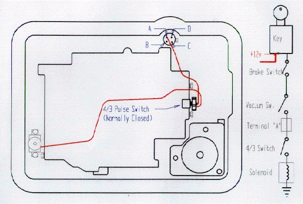 This is the usual 700R4 wiring setup taken from a
shop manual.
This is the usual 700R4 wiring setup taken from a
shop manual. 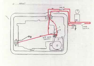 This is
my Lockup wiring setup... It is similar to the other pictured, except much simpler.
A 4th gear lockup kit from Darryl Young racing transmissions. If you move the
'Pulse switch' down one plug in the picture, it will be installed in the 4th
gear oil gallery. You will only lockup in 4th with this setup. It prevents
that hunting and pop-in/pop-out sensation. Also a wire was spliced from the solenoid
power lead off the pulse switch back through the weatherpack connector
(D) to an LED light on the dash to let me know that the lockup solenoid has power
to it. If the pulse switch fails then no light. In the event the switch does
fail, the scheme also includes a reverse hot 12V toggle switch on the dash to
bypass the switch and supply power to the solenoid and the LED to aid in
troubleshooting and to assure lockup. With this setup, you can lockup in any
gear bypassing the Pulse switch AND it won't ruin your system. Further, I don't
use all that circuitry shown on the right side of the photo. My wiring scheme is
a 2 amp fused line connected to the accessory buss and runs directly to (A) on the
weatherpack connector. As soon as you drop out of 4th gear, the lockup quits.....
.......works like a charm................./rfj
This is
my Lockup wiring setup... It is similar to the other pictured, except much simpler.
A 4th gear lockup kit from Darryl Young racing transmissions. If you move the
'Pulse switch' down one plug in the picture, it will be installed in the 4th
gear oil gallery. You will only lockup in 4th with this setup. It prevents
that hunting and pop-in/pop-out sensation. Also a wire was spliced from the solenoid
power lead off the pulse switch back through the weatherpack connector
(D) to an LED light on the dash to let me know that the lockup solenoid has power
to it. If the pulse switch fails then no light. In the event the switch does
fail, the scheme also includes a reverse hot 12V toggle switch on the dash to
bypass the switch and supply power to the solenoid and the LED to aid in
troubleshooting and to assure lockup. With this setup, you can lockup in any
gear bypassing the Pulse switch AND it won't ruin your system. Further, I don't
use all that circuitry shown on the right side of the photo. My wiring scheme is
a 2 amp fused line connected to the accessory buss and runs directly to (A) on the
weatherpack connector. As soon as you drop out of 4th gear, the lockup quits.....
.......works like a charm................./rfj
Here's another tack....
For converter lock-up control I used B&M Part NO. 70244. It will works
much better,and safer than a "foot switch". The converter needs to
un-lock when you slow down or brake during a panic stop. It is an
adjustable control module that provides driver control of the speed
where lock-up takes place. The dash mounted electronic control module
has a slide type potentiometer to adjust lock-up speed and two LED's
that indicate the lock-up clutch status (on/off). It receives a variable
voltage signal from the speedometer cable mounted sensor. It is
recommended that 4 speed overdrive lock-up speed not be set higher than
45 MPH. Operation in fourth gear (overdrive) without the converter cluch
lock-up can result in transmission and engine overheating. The system
works extremely well in my Avanti along with the B&M shift kit
modification.
Regards, Jack
avanti1@webtv.net Nov 2001
---------------------------------------------------------------------------
The usual TV cable replacement unit has a plastic housing that fits into a bracket
by the carb. The housing is ratcheted and held tight by a sliding lock. The
method is to connect both ends of the cable, release the lock, push the butterfly
shaft to WOT and lock the ratchet fitting.
My application does not have room
for this bracket in the correct place, so that plan was discarded.
A number of sources were queried, as to what they would do in such a situation and
not one could give me a decent answer. These included transmission repair
individuals and service station personnel. I tried to find out the movement
relationship between the throttle plate and the TV cable to relate that to an
adjustment. No luck there either.
Since both my engine and trans were Jasper units,a call was placed to Jasper's Technical Support. The immediate response was to adjust the TV cable with a transmission Main Line pressure guage. This is the ONLY way of assuring correct adjustment.
So obviously the canned scheme outlined above 'fit the cable, release the lock, go to WOT", etc is a guess in itself.
A guage cost me $40.00. Quite cheap for insurance on a $1500.00 transmission.
The guage comes with a 4 foot hose and a package of different fittings, probably some metric. The attachment point is right above the shifter detent on the driver side.
The pressures, with the engine HOT, in PARK at IDLE should read 70 - 75 PSI(*1). Pulling the cable to the point where Wide Open Throttle (WOT) exists, the pressure should read 170 - 175 PSI.
(*1) these pressures relate to my Jasper transmission, a remanufactured '84 police
cruiser unit, so it's fairly heavy duty AND Jasper has built upon that with their
own procedures for remanufacture.
There are many variations in pressures depending on models and applications.
Refer to a reliable reference manual for yours or email me if it's between '82 &
'86 and I'll look it up for you
Regarding the WOT adjustment...
While the engine was running,
1) I set the idle pressure by pulling the cable to the proper point and tightened
it to the throttle connection.
2) Detached the TV cable from the throttle linkage, pulled it until it registered
the 170PSI and marked the TV cable.
3) Cut the engine off, reattached the cable and measured the throw of the carb
linkage vs the mark on the cable.
As it winds up, the pressure increase is relative and correct, providing you have
the geometry of the throttle and TV cable connections correctly spaced. As you
recall, I had to make the carb linkage bracket to fit outside the R-3 airbox. This
was a ground up creation using various specs of carb linkages, advise, mag articles,
etc.... For those using factory connections, it's a given that your secondary
pressure would be satisfactory.
![]()