
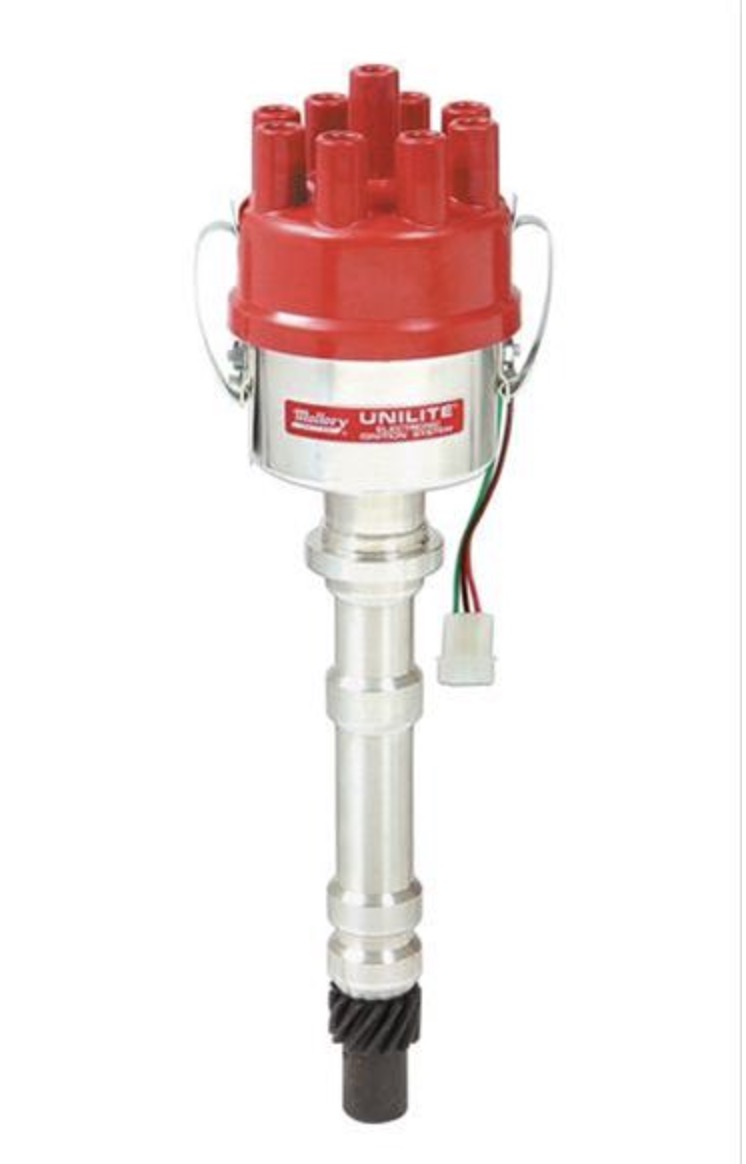
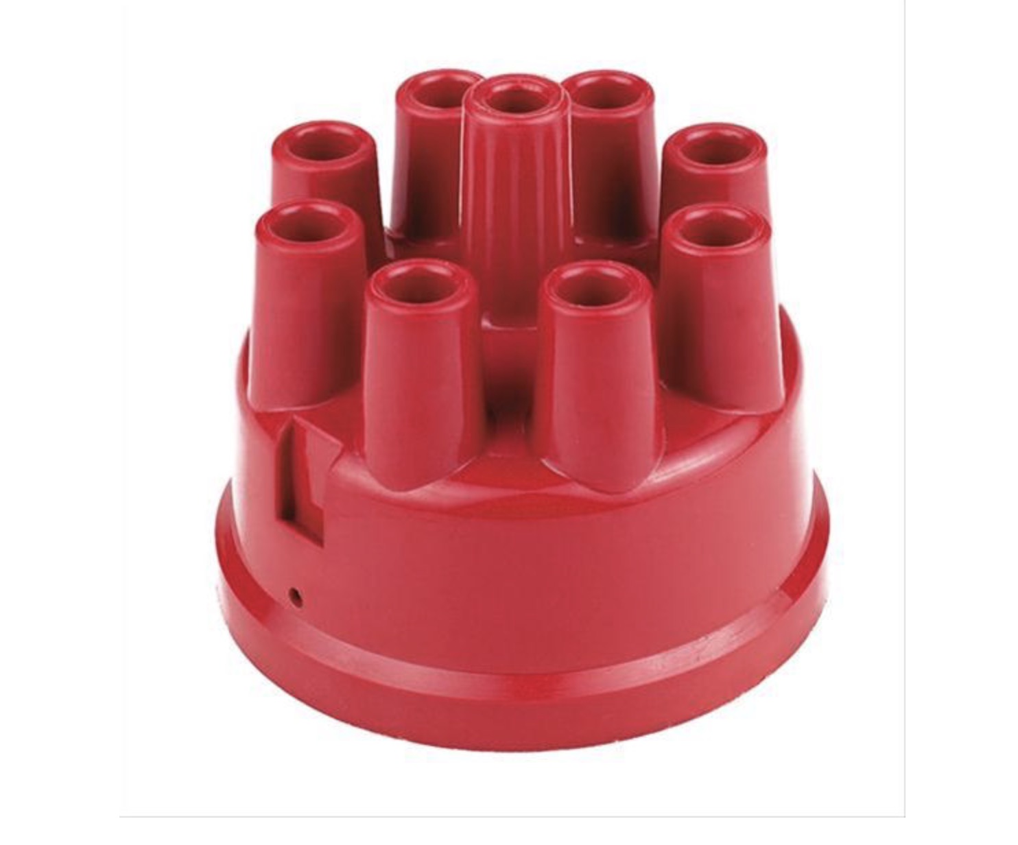
| The Mallory Unilite Distributor |
|
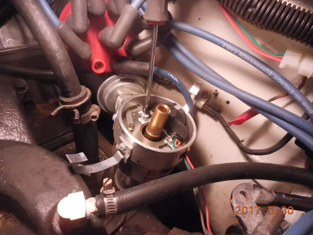
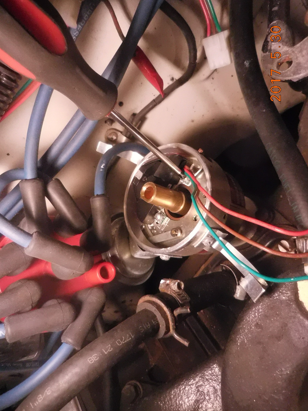
Remove the 2 screws holding the module down. Note the gap between the shaft and plate. Stuff tissue paper in her to prevent losing a screw down the opening
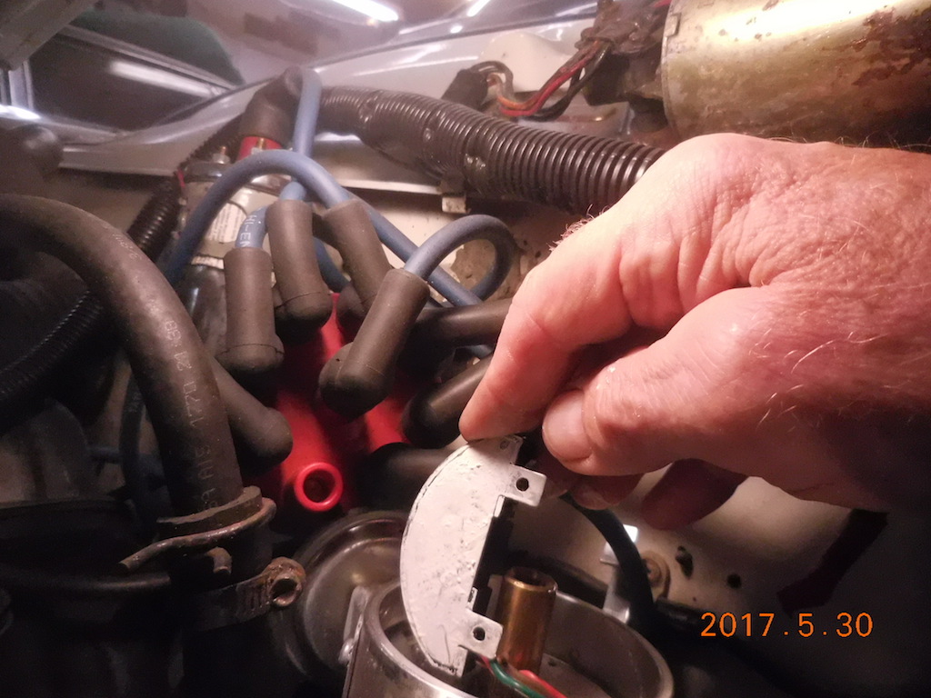 The underside of the module is covered with THERMAL conductive paste. This is used to wick HEAT away from the IC chip inside
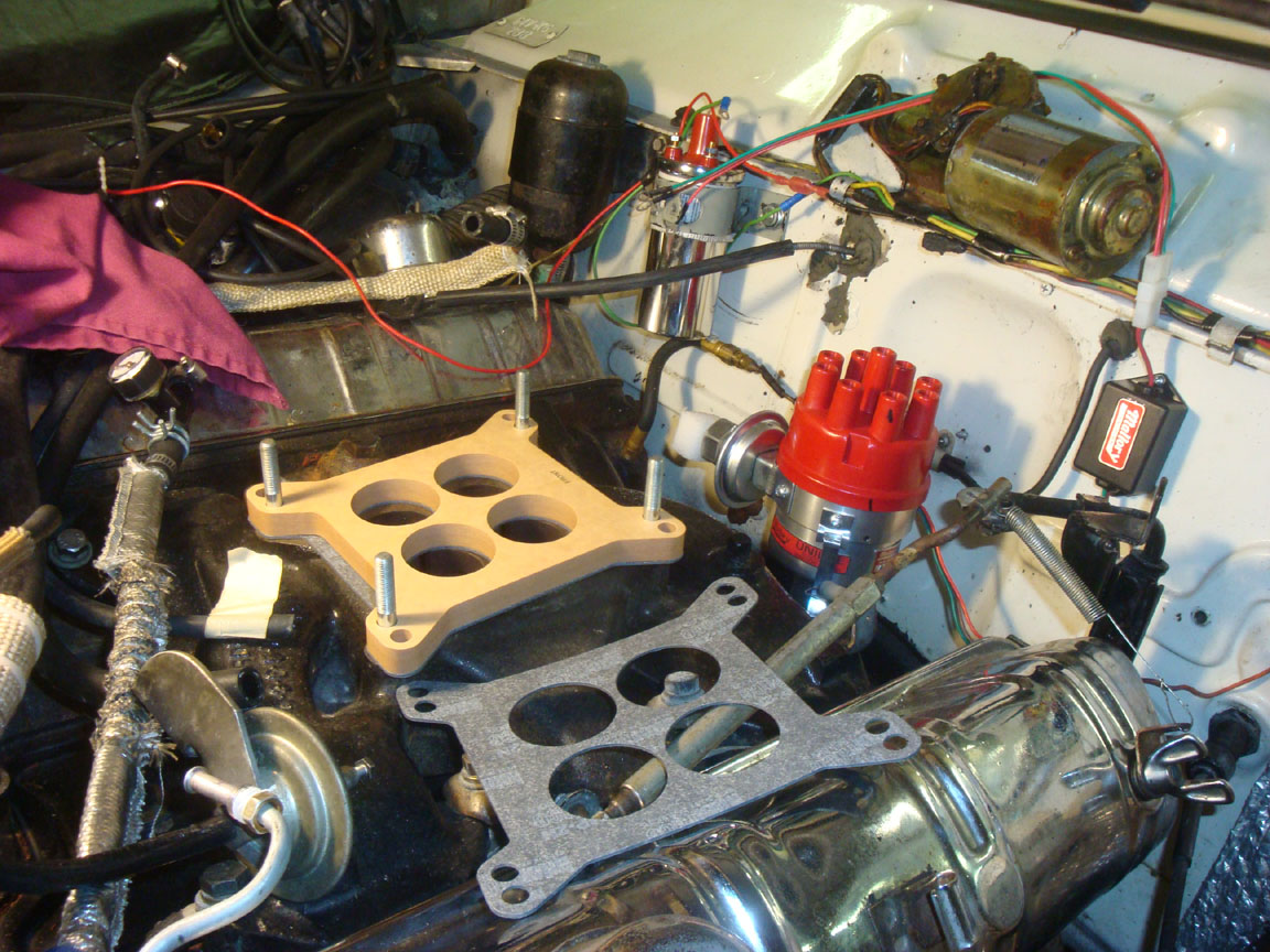
Note the wires pass thru a port in the distributor
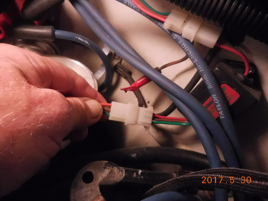
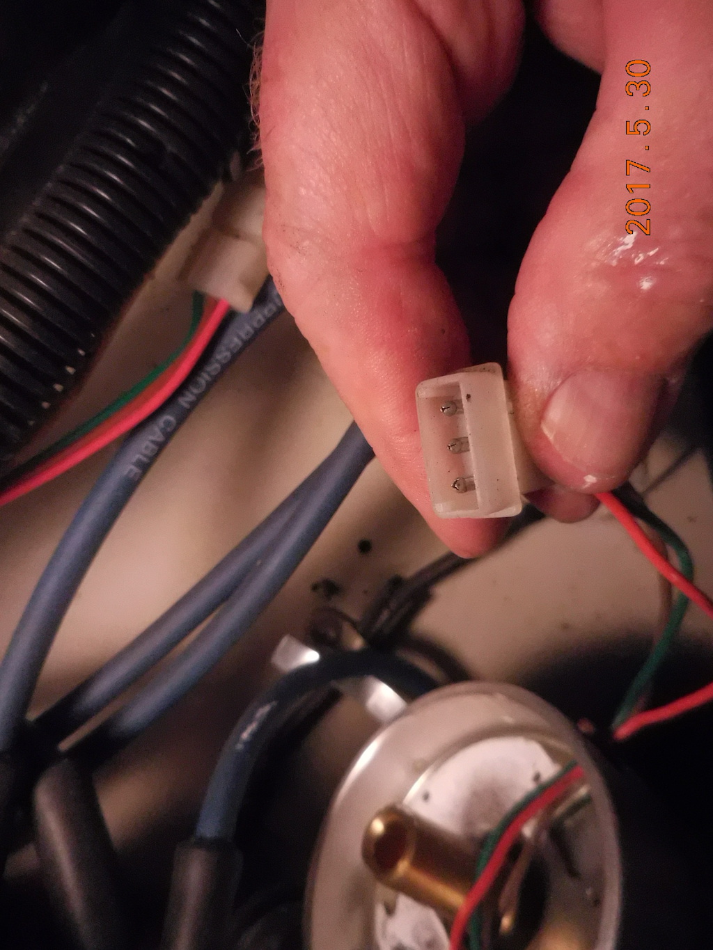 The pin locks must be compressed with a small screwdriver to allow the wires to be released
Or you can just CUT the wires
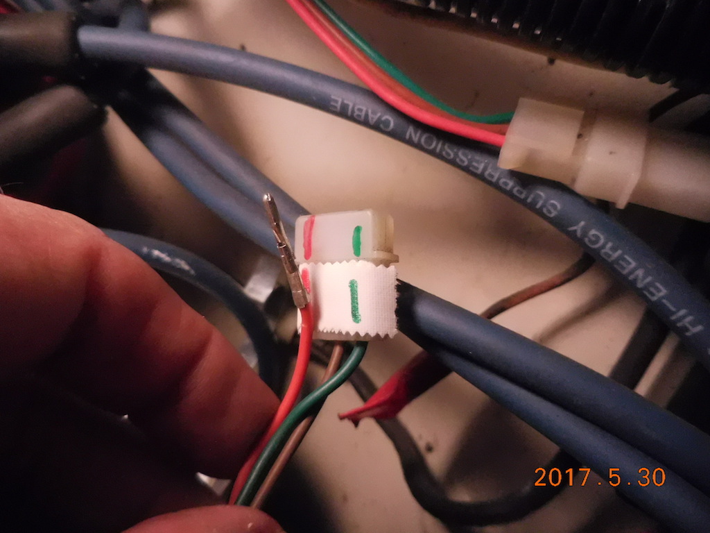 Mark the plug as to the correct wiring for he new module
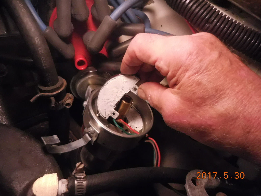
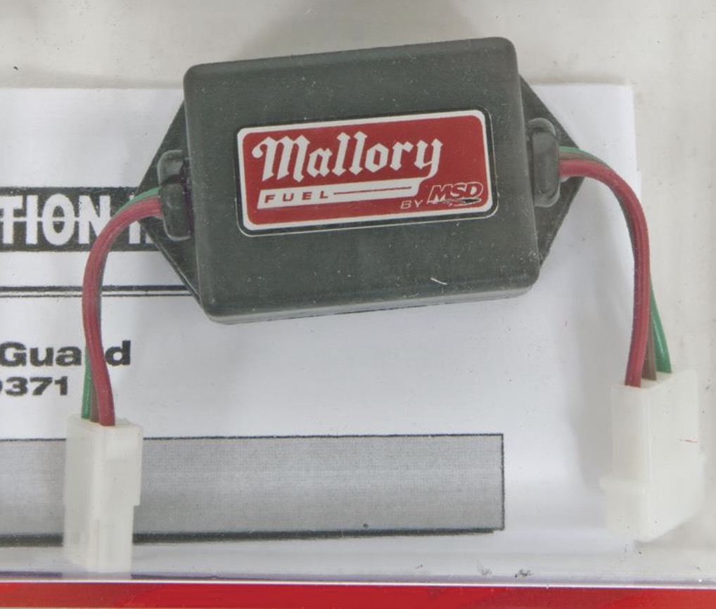
 (IMPORTANT)Spread the supplied THERMAL conductive paste from the repair kit on the bottom of the Module DO NOT USE Dielectric grease on the module base, but it's ok to use on the wiring connector Fasten it into the distributor Thread the wires through the port in the side of the Distributor Reattach to the Surge Protector Done!
|

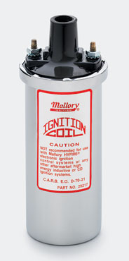
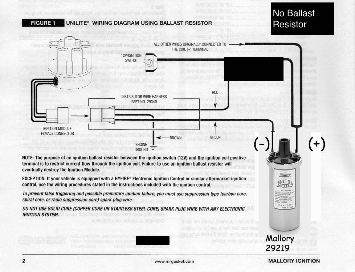
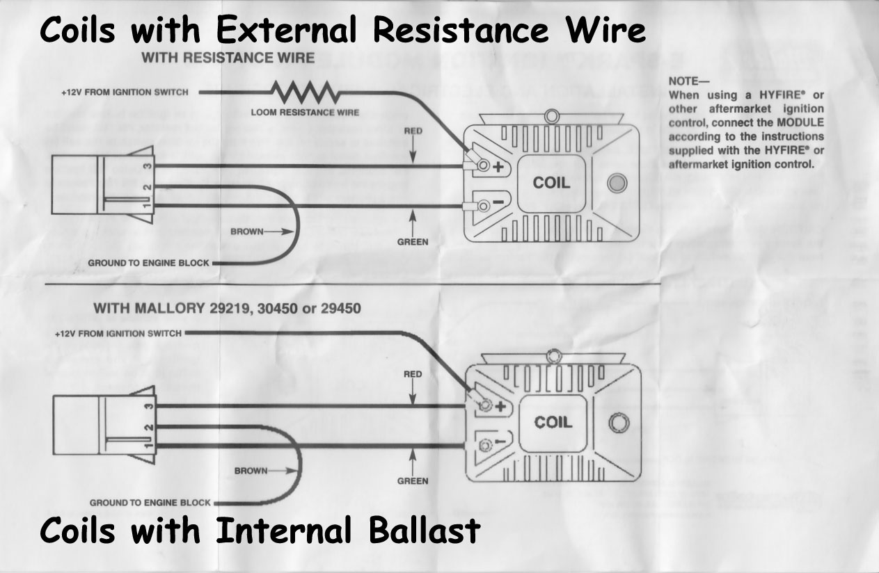 Note the Non-Ballast Coil Numbers on the sheet