Bob's Studebaker Resource Website
Studebaker & Avanti Pertronix/tachometer install with Pertronix High Voltage Coil
( Thanks to Bob Proodian (Fairfax, VA) and Turning Wheels for providing information that led to this resolution
Bob's Studebaker Resource Website
Studebaker & Avanti Pertronix/tachometer install with Pertronix High Voltage Coil
( Thanks to Bob Proodian (Fairfax, VA) and Turning Wheels for providing information that led to this resolution
In a 62-64 Studebaker (any model), installation of a Pertronix Ignitor Module, with the Hi-Voltage coil will pose a couple problems to the owner. There are no issues if you use the factory standard coil, however the Hi-Voltage coil supplied by Pertronix has an internal resistor (1.5Ohm). Prior to 1962, the factory used an External resistor near the coil for the ignition to function properly. During 1962 and later, factory wiring changed to a 16 gauge Pink thermistor wire from the ignition switch to the coil, which reduces voltage and prevents point and coil problems while running. Installation of the Pertronix Hi-Voltage coil requires that the owner remove the pink thermistor wire, however doing so will disable the tachometer. (see below)
In order to use the Hi-Voltage Pertronix coil AND have the tachometer operate correctly, read the rest of the page..
|
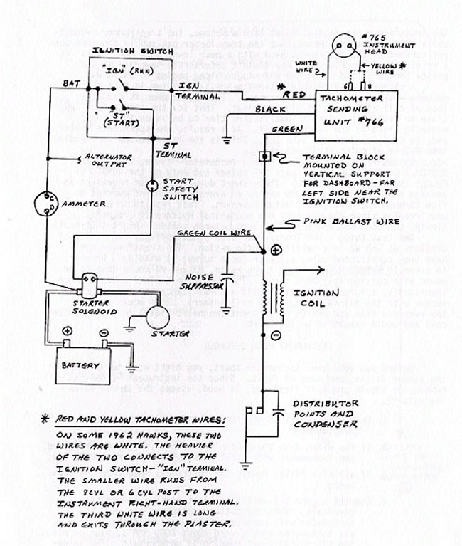
The Factory shop manual does NOT provide the schematics shown here and without having it available, one might think that the pink wire to the coil comes right from the IGN post on the ignition switch. ( That would be the normal wiring procedure when using a thermistor wire in an ignition circuit. The thermistor wire reduces voltage to the coil, preventing burned points and coil failure. In Studebaker cars without the thermistor wire, an external resistor is mounted near the coil and is readily obvious. It gets fairly hot when the engine is running) In 1962 and later Studebaker cars with factory installed tachometers, the pink thermistor wire <----( called ballast wire in the schematic) travels back from the coil and is joined to the Tachometer sender output (green) wire, at a junction block, attached to the dash brace, on the left underside of the dash. So, if you remove the pink wire and run a straight 12 volts from the IGN switch to the coil, you have disconnected the tachometer sender and the tachometer will be disabled.
Effectively, with factory wiring, all the voltage from the IGN switch, intended for the coil, passes through the tachometer sending unit and the fluxuation in voltage by the thermistor, does NOT effect the function of the tachometer sender. A bit more digging and paperwork from other owners show that Studebaker Tachometer senders operate on a transistor triggering method. |
|
 ( no tachometer)
|
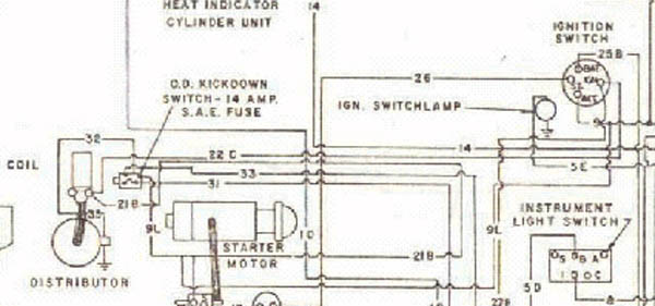
When the coil is changed to a type that does not need a ballast resistor or thermistor wire, things change considerably, especially when you look at how a Pertronix is wired to the coil. The distributor is no longer required to be the ignition circuit ground. It merely contains the solid state module from Pertronix. <--------Using the Shop manual (left) to interpret the ignition circuitry, it shows the coil (+) teminal having a pink wire and a green with black tracer. The green is a shunt from the starter solenoid to the coil to provide an extra shot of 12 volts when the starter is cranking. The coil (-) terminal is connected to the Distributor and routes through the points, so the make/break action will ground the field coils and provide a high tension spark for the plugs.
| |
|
(Revised for clarity - Oct 2015)
for after delivery tachometer install with Studebaker Ignition Coil
|
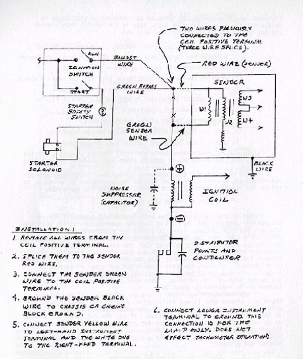
<----------Using the schematic on the left, note that the ALL the voltage provided to the coil, again passes through the tachometer sending unit, however the routing is changed from the earlier example. This is the factory recommended circuitry for a 62 model whose owner wanted a tachometer added after delivery. . A few things change with the Pertronix......the pink wire is unnecessary and removed (or disconnected and ignored) The sender RED lead is connected to the IGN post, with the green/black from the coil. The GREEN sender lead is then extended and run solely to the (+) terminal on the Hi-Voltage coil. All the voltage for the ignition runs through the tachometer sender.
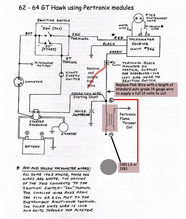
The Pink wire has been isolated and replaced with a length of 14 gauge from the terminal block on the dash brace, to the coil. The 1181 or 1183 Module black is connects to the (-) side of the coil and the RED is connected to the (+) side. You're done! |