Bob's Resource Website
Avanti Caliper adjustment - Studebaker Avanti
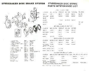
1963 - 1964 Studebaker Disc brakes 1963 - 1984 Avanti / Avanti II Bendix - Dunlop or Sumitomo - Dunlop (Toyota)fixed iron calipers. All use NAPA # or any aftermarket manufacturer 702 pads.
After rebuilding or removing your calipers for any reason, where the shim packs have been disturbed.......... The disc brake system on early Studebakers and Avantis into 1984 are of the fixed caliper design. The bridge which holds the piston assembly is solidly fixed to the spindle adapter. They do not 'float' when actuated as in almost all later model cars. Fixed calipers are of superior design and are more expensive to manufacture. They work very well when adjusted to specification and are maintained. Briefly, to cover both adjustment dimensions; You must strive to enable each brake pad to squarely contact the rotor. In addition, the amount of piston travel on each side must be evened out. Failure to do this can result in a variety of problems. The small size of the pad actually compounds the problem, since a slight twist in the pad, being caused by uneven adjustment, can cause the piston to wedge in the cylinder bore and jam. Further, the piston travel, is limited by design and cannot cause a worn pad to contact the rotor. However, once a piston is at the end of its reach, that pad is now useless, although it will slightly drag when applied, and no amount of foot pressure will make it function. This in turn, significantly diminishes, although not totally, the amount of braking ability on that side of the car. Early signs could include 'pulling' to one side'.
The calipers are approximately 5 inches long and mount squarely over the
rotor. This makes 4 adjustment points. P1 and P3 are on the inside of the
rotor at each end of the caliper, points P2 and P4 are at the outer side of
the rotor and caliper. The distance between *(points 1 - 2 and 3 - 4) are
adjusted first. To realign the calipers, centering them over the rotor is a 2 step process. First, to set an average distance between the inner arch of the caliper and the inner side of the rotor, next to balance the distance between the rotor and caliper at the front and rear. Do this with caliper pistons recessed into the cylinder, ready for new pad installation, but WITHOUT the pads. If the shims have fallen off (hard to prevent) the mounting bracket, try this (without pads installed) . Make sure all shims have been removed. Mount the cleaned caliper on the cleaned bracket, place spacer and lock washers on the mounting bolts and tighten bolts snug enough to hold caliper in place, but not torqued to spec.
Get a notepad and write these numbers down.
ADD P1 and P3 and divide by 2 to get the average distance (D1), then divide D1 in half once more to obtain (D2) or half that distance. D2 should be the start space between each corner of the caliper and the appropriate rotor surface.
Remove the caliper. Bob Johnstone (rfjohnstone at cox.net) May 2000
Just make sure that the spacing is the same at all four bracket corners.
No more than .008 difference side to side, and .002 end to end. You'll
tighten the bolts a few times before you get it right.
Bob Ziff
1. Make sure you lube the wheel bearings and adjust them to spec before you
shim the caliper.
2. Use a dial indicator to check the brake rotors for axial runout. You
can't accurately shim a warped rotor. A rotor may show too much runout
(more than .025"), but not be warped. Early Saab service manuals actually
suggest shimming the rotor at appropriate lug bolts around the hub to
achieve minimal runout before beginning to shim the calipers. A bit harder
to do on Studes, but with OEM rotors impossible to find these days, anything
to save one.
3. Do a trial fit and get the clearances close to where you want them. Then
mount the tire/wheel, spin it, wiggle it, apply the brakes a couple of
times, then remove the tire/wheel and check the clearance again. When you
get the clearances to stay where you want them, remove the caliper mounting
bolts one at a time, apply plenty of locktite, torque to specs, mount the
wheel/tire and torque the lug nuts to spec.
Jack Vines
|