Brake Valves: Operation & Service, Bill Williams, Brake & Front End, May 2000
Brake valving represents the least understood area of the conventional brake system. There are several reasons for this.
• They are thought to be "bulletproof" and last forever;
• You need special tools to check them;
• They won't affect normal brake operation; and
• Most training does not cover them in any detail.
For these reasons and others,
most technicians do not take the time to understand what role each of
these valves plays in the operation of the brake system. Not having an
understanding of this prevents the technician from knowing when to add
these valves to the list of possible causes when diagnosing a specific
brake problem. These valves can and do fail depending on the valve's
design and location on the vehicle.
There are three main types of brake
valves in use on today's brake systems: metering valves, proportioning
valves and pressure difference switches. Although not actually a valve,
the pressure differential switch is usually grouped together with brake
valves when discussing brake system operation. Before we proceed, we
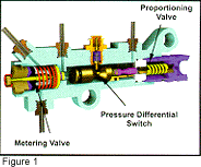
have to get some terminology straight. The valve pictured in Figure 1
is not a proportioning valve. The entire valve assembly is called a
combination valve. Modern vehicles house more than one valve in a
common housing to save on production costs.
Proportioning Valve
The proportioning valve is designed to prevent rear wheel lockup
during panic braking. It is needed for two main reasons - most vehicles
use drum brakes in the rear and all vehicles experience weight transfer
during a panic stop. Rear drum brakes are hydraulic over mechanical in
design. If too much pressure is supplied to the wheel cylinders, lockup
will occur. All vehicles, those with both rear drum and rear disc
brakes, will experience weight transfer during a panic stop. When
weight is taken off the rear wheels during a panic stop the tendency
for the rear brakes to lockup will increase. The proportioning valve is
designed to limit the pressure to the rear brakes during a panic
braking situation.
The most important point to understand
about proportioning valves is when they work - only during panic
braking. This means that a vehicle could potentially go its whole life
without ever using its proportioning valve. Think about the little old
lady that drives to and from church and the grocery store. It is
possible that she will never have the need to make a panic stop and
therefore never activate her proportioning valve. The other half of
that equation is all those who drive near her will probably get a
chance to see if their proportioning valves work!
Hydraulic Proportioning Valves
Most vehicles incorporate a proportioning valve that uses the
pressure in the brake system to know when a panic braking situation is
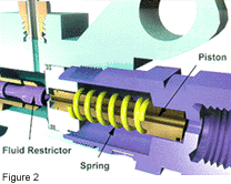
taking place. A typical proportioning valve is pictured in Figure 2 on.
The main components of the valve include the piston, spring, fluid
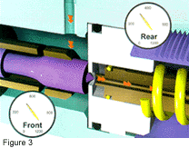
restrictor and valve housing. During normal braking the fluid flow is
unrestricted through the proportioning valve, as in Figure 3.
This is where the proportioning valve
spends most of its life. The spring prevents the piston from moving
until a certain pressure is reached. This pressure is known as the knee
point. When the vehicle experiences a panic braking situation the
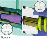
system pressure will increase dramatically. When the pressure reaches
the knee point it is strong enough to compress the spring. As the
piston moves, its opening presses against the fluid restrictor, as
shown in Figure 4. This starts to limit the pressure to the rear
brakes.
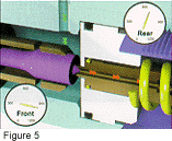
If the panic braking situation
continues and system pressure increases past the knee point the piston
will be pushed tightly against the fluid restrictor which shuts off any
more pressure from reaching the rear brakes (see Figure 5). The knee
point and maximum pressure allowed to the rear brakes vary with each
vehicle and the numbers shown in the previous figures are for reference
only. When the brakes are released, the spring pushes the piston back
to its rest position, which opens the fluid passage to the rear brakes.
There are other designs of hydraulic proportioning valves. They operate
different internally, but accomplish the same outcome - prevent rear
lockup during panic braking. Also realize RWD vehicles use one
proportioning valve while FWD vehicles use two. On a FWD, each rear
brake is on a separate circuit so two valves are needed.
Hydraulic-activated proportioning
valves have some disadvantages. Since their only input is the system
pressure, they have no way of knowing if the vehicle's load changes.
Ideally, if the rear of the vehicle is loaded, the rear brakes should
be allowed to do more of the work. The other disadvantage of older
hydraulic-activated proportioning valves relates to when there is a
front hydraulic failure. If there is no front pressure, the rear brakes
must do all of the stopping and excessive pedal pressure will be
needed. Guess what the proportioning valve "thinks" is happening? You
got it - panic braking. It will do the job it is supposed to, which is
to limit the rear brake pressure at a time when you really need it.
Diagnosing Hydraulic Proportioning Valves
Whether or not you take the additional steps to inspect or
diagnose a vehicle's hydraulic proportioning valve will depend on the
following:
Could the customer's compliant involve the proportioning valve?;
What is the condition and location of the combination valve?; and
What type of proportioning valve does the vehicle have?
The proportioning valve will only
be added to our list of possible causes if the customer's complaint
involves rear-wheel lockup under panic braking. We must ask the
customer when the rear wheel lockup is occurring - light to normal or
heavy to panic braking? If the answer is panic braking, the valve is on
our list, but it won't be the only thing on our list (see April's
article on rear-wheel lockup for more information). The valve's design
will determine how and when we are going to diagnose it.
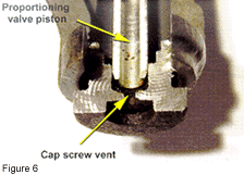
The design of some proportioning valves
allows two things - more chance for failure and an easy way to diagnose
them. If we take a look at the proportioning valve in Figure 6 we will
see the cap screw that holds the piston and spring in place is vented.
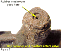
In the vent hole is a small rubber "mushroom" that is supposed to
prevent any moisture from entering the cap screw. If this style of
valve is mounted low on the vehicle, as in most rear-wheel-drive
vehicles, it can be exposed to a high degree of moisture. This is
especially true where road salts are used for snow and ice removal. The
moisture can corrode the cap screw and allow water to enter into the
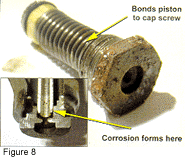
area where the piston travels in the cap screw (see Figure 7). This
causes the inside of the cap screw to corrode which bonds the piston
and cap screw together (see Figure 8.). Normally when the cap screw is
removed, the cap screw, spring and piston are separate pieces. This
corrosion prevents the piston from moving when a panic braking
situation occurs.
The same thing that allows the
valve to fail is what will allow us to check it - the cap screw vent
hole. First determine if the valve is a good candidate by its external
appearance. If the outside of the valve and especially the cap screw
are corroded then it is a good candidate. Remove the rubber mushroom
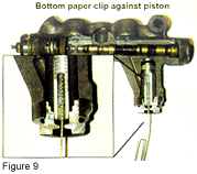
from the cap screw. Next insert a paperclip so that it bottoms out in
the piston as in Figure 9. Have an assistant start the vehicle and
apply heavy pedal pressure to simulate a panic braking situation. The
paperclip should push against you and travel about 1/32" to 1/16" as
the piston moves. If the paperclip doesn't move the piston is seized in
the cap screw and the valve will have to be replaced. This test will
work on any proportioning valve that is vented through the cap screw
and should be part of your normal inspection if the valve's exterior
condition merits it.
Most proportioning valves are not vented
through the cap screw. There is not a quick check for these types of
valves. These valves should only be checked if the customer's complaint
indicates a possible proportioning valve problem. Most shops do not
have pressure gauges so the process used to diagnose the problem will
have to be a process of elimination. All other possible causes will
have to be checked before the proportioning valve is condemned.
Pressure gauges are the best way
to diagnose a failed proportioning valve. A gauge is installed into the
front and rear hydraulic circuits. The vehicle is started and the brake
pedal is applied with heavy pedal pressure to duplicate a panic braking
situation. The front and rear pressures should be different. Most
manufacturers do not publish these pressures. The rear brakes usually
are "shut" down between 500 and 800 psi while the fronts can climb to
well over 1,200 psi. What you are looking for is whether the rear
pressure has been limited. If the pressures are equal then the valve is
not working and will have to be replaced to correct the problem.

Mechanical Proportioning Valves
Some vehicles use ride height to sense what should be done with the
rear brakes. If a vehicle is in a panic brake situation, weight is
transferred to the front and rear ride height changes. Likewise, if the
rear of the vehicle is loaded then the rear ride height changes.
Engineers came up with "smart" proportioning valves that use ride
height to determine what to do with the rear brake pressure. These
valves have several different names depending on who is talking about
them. They can be referred to as "load sensing proportioning valves,"
"height sensitive control valves" or "smart proportioning valves."
Instead of using hydraulic pressure they use a mechanical linkage to
the vehicle's rear suspension as shown in Figure 10. There are many
different variations of this type of valve, but all do the same job.
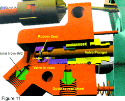
There are three main positions
for these types of valves. The position it spends most of its life is
where the vehicle is operating at normal ride height and performing
routine stops (see Figure 11). In this position the rear brakes are
allowed to do their fair share of the vehicle's braking.
The next most common position for the
valve is when the vehicle is carrying a load. When the vehicle is
loaded the valve is opened further (Figure 12) to allow the rear brakes
to do more braking. This is one area that sets it apart from its
hydraulic counterpart.
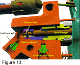
The third possible position occurs
during panic braking. If a panic braking situation occurs then weight
transfer takes place and rear ride height increases (see Figure 13).
When this takes place, the linkage to the valve restricts pressure to
the rear brakes to prevent rear-wheel lockup.

One of the most important points
to understand about these valves is because they rely on ride height to
work, their adjustment will need to be checked periodically. As a
vehicle ages, its ride height can change. This will affect the smart
valve's operation. If the vehicle's ride height is lower than it should
be and the valve's adjustment is not changed to compensate for this it
will allow the rear brakes to work longer than they are supposed to.
The valve "thinks" the vehicle is in a constant loaded condition.
Another related point is that nothing
can be done to alter ride height without affecting the valve's
operation. The addition of helper springs, air bags or even high
pressure gas shocks can be enough to change the valve's operation.
Anything that increases rear ride height will cause the valve to
"think" a panic braking situation is taking place. It will restrict
fluid pressure to the rear brakes and cause the fronts to do more work.
The addition of these items can also change how soon weight transfer
takes place.
There are many vehicles equipped
with some variation of smart valve. Plymouth and Dodge Mini-vans,
Taurus and Sable sedans, Volkswagen and Audis, Windstar vans, Toyota
Pickup and 4-Runner, and many of the 1/2- and 1-ton domestic pickups
all have load sensing proportioning valves of some sort. Keep in mind
that all FWD vehicles use a valve that actually houses two valves, not
one. These vehicles are diagonally split and need one valve for each
rear wheel.
Adjusting & Diagnosing Mechanical Proportioning Valves
 The adjustment of these valves should be checked periodically. This
is especially true if anything is done to alter the vehicle's ride
height. The steps involved in adjusting these valves vary greatly from
one manufacturer to another. Generally the domestic procedures are
fairly simple when compared to either the European or Japanese.
Domestic adjustment procedures usually do not involve the use of
pressure gauges, while both the European and Japanese require them. It
is not possible to cover these procedures in this article, so when
valve adjustment is necessary consult the appropriate service manual.
Diagnosing the operation of these valves
holds similar challenges. Depending on the type of hydraulic system
valve failure can come in different forms. If the vehicle has a front
to rear split system (RWD) then the valve can fail in two typical ways
- open or closed. If the valve fails open or stays open too long it
will cause rear brake problems. If the valve fails closed or stays
closed too long it will cause front brake problems. On the other hand,
if the vehicle is a FWD with a diagonal split hydraulic system then the
possible combinations increase. Since there are two valves, it results
in eight possible failure combinations.
The best method to check valve
function is by using a set of pressure gauges. If pressure gauges are
not available, a primitive check can be made. If you understand how
these valves work then you can perform a basic function check by
checking fluid flow at different ride heights. The steps required for a
RWD are slightly different than those for a FWD. The reason is the FWD
valve has two valves so each rear wheel must be checked separately. To
check a FWD vehicle, start with the tires on the ground, open the right
rear bleeder and have an assistant slowly push the brake pedal half of
the way down. Note the size and strength of the fluid flow. Close the
bleeder and do the same with the left rear. Make sure your assistant is
consistent with the pedal force. The size and strength of the streams
should be close to equal. With the tires on the ground the valve should
be open and fluid flow should be uninterrupted. If one of the streams
is considerably less than the other chances are the valve is stuck
closed. Next raise the vehicle by the frame and let the rear wheels
hang. This simulates a panic braking situation and should restrict the
valves. Repeat the previous steps and note whether there is a
difference from side to side and from when the tires were on the
ground. Theoretically, the streams should be reduced with the wheels
hanging if the valves are working. If both sides are doing the same
thing, both open when they should be closed or both closed when they
should be open, try adjusting the valve first. If adjusting the valve
doesn't correct the problem then replacement is in order. If there is a
side-to-side difference, it is internal and the valve should be
replaced.
Metering Valve
 The metering valve is a balance or timing valve. It is used on most RWD
vehicles that have disc brakes on the front and drum brakes on the
rear. Disc and drum brakes apply at different times. Disc brakes will
apply immediately while drum brakes take a while to apply. The reason
for this is the return springs in the drum brakes prevent the drum
brakes from working until a certain pressure is reached. Disc brakes
have no return springs so they apply instantly. The metering valve's
job is to "hold" the front brakes off until the rear brakes start to
apply. For this reason it is also known as a "hold off" valve. If no
metering valve were used the vehicle would nose dive and premature wear
could occur in the front brakes.
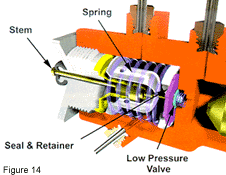
The metering valve consists of the
following main components - stem, diaphragm, spring, seal and retainer
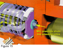
and low pressure valve (Figure 14). Metering valve operation takes
place in three stages. When the brakes are first applied the low
pressure valve closes off the passage to the front brakes (see Figure
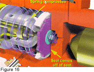
15). Once the pressure in the system is high enough to overcome the
return springs in the rear drum brakes it also is high enough to just
open the metering valve (see Figure 16). This is known as the blend
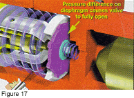
pressure. Once the metering valve starts to open and pressure is
allowed against the diaphragm, the difference in pressure on each side
of the diaphragm causes the valve to fully open (see Figure 17). At
this point both the disc and drum brakes will apply at the same time
and balanced braking will be achieved. Unlike the proportioning valve,
the metering valve works every time the brake is applied.
The majority of RWD vehicles use
metering valves. They are usually part of the combination valve. FWD
vehicles do not use metering valves. A FWD vehicle does about 80
percent of its braking with the front axle. There is no need to "hold"
them off.
Diagnosing Metering Valves
The diagnosis of a metering valve is quite simple. All metering
valves use a stem. Depending on the design of the valve, the stem will
either protrude through or be underneath a rubber dust cap. To check
the operation of the metering valve simply observe the stem during the
brake apply and release cycle. It should move out when the brake is
applied and return to its rest position once the brake is released.
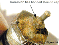
Most metering valve failures are caused by external not internal
problems. The rubber cap that keeps moisture out eventually dry rots
and/or the cap screw corrodes. Either one of these will allow moisture
to enter around the stem. The area between the stem and cap screw
corrodes, which eventually bonds the two together (see Figure 18).
The metering valve can fail in one of
two common positions. It can fail where it is stuck in an open
position. This would be the same as not having a metering valve on the
vehicle. The vehicle may experience a nose dive condition, and if the
valve has been stuck open long enough there may be some premature front
pad wear.
The metering valve can also stick
in a position where it cannot open all of the way. This would be
similar to having a faucet between the front brakes and the master that
is only part way open. This usually causes a lack of stopping power
because the front brakes are not working at 100 percent. If the
metering valve stem fails to move when the brake is applied and
released it needs to be replaced regardless of the vehicle's symptoms.
The metering valves with the highest
failure rate are those that are mounted low on the vehicle. These
valves are exposed to the elements just like the low mounted
proportioning valves. The failure rate for these valves is much higher
than what people think. In the snow belt areas it can be as high as 20
to 30 percent.
Pressure Differential Switch
All modern vehicles are equipped with a red brake warning light.
One of the purposes of this light is to inform the driver of either a
fluid loss or pressure loss condition. Fluid level switches are used
for fluid loss and pressure differential switches are used for sensing
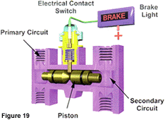
pressure. Pressure differential switches use a piston that is exposed
to both the primary and secondary hydraulic circuits as in Figure 19.
The pressure differential switch consists of the piston, electrical
contact switch, wiring and warning light.
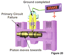
If the vehicle experiences a hydraulic
leak or failure of either the primary or secondary half of the master
cylinder, a difference in circuit pressure will be created. The
pressure from the functioning portion of the hydraulic system will
force the pressure differential piston toward the side with the
pressure loss. The movement of the piston will cause the electrical
contact switch to go from open to closed as in Figure 20. This will
complete the ground circuit to the red warning light and will
illuminate it.
The pressure differential switch
piston never moves until a pressure difference occurs. The bore in
which it travels becomes corroded and tarnished over time. When the
piston does move, it does not always want to return after the necessary
repairs are made. The most effective method to re-center the piston is
to repair the failure, bleed the system and then create a pressure loss
opposite what moved the piston in the first place. If the original
failure was a broken rear brake line, fix the line and bleed the rear
brakes. Next open a front bleeder and spike the brake pedal a couple of
times taking care not to exceed half pedal travel. Tapping on the side
of the valve with a rubber or brass hammer can also aid in the process.
If after using this method the piston still won't re-center, then the
combination valve should be changed.
Special Purpose Pressure Differential Switch
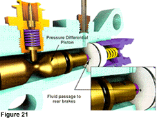
There are a number of pressure differential switches that perform a
second function. In addition to completing the ground to the red
warning light, they also shut off the fluid flow to the rear brakes if
a rear hydraulic failure has occurred. The fluid flow to the rear
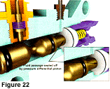
brakes is through the ports in Figure 21. If a rear pressure loss
occurs then the pressure differential piston moves toward the rear
brake circuit and closes off the fluid passages to the rear brakes as
in Figure 22. When dealing with this type of valve you must re-center
the valve before the rear brakes can be bled. Bleed the lines at the
master cylinder and the fitting on the valve. Open a front bleeder and
spike the brake pedal a couple of times taking care not to exceed half
pedal travel. This usually will re-center the piston. If it won't
re-center, the combination valve will have to be replaced.
In closing, there are many
variations of brake valving in use on today's vehicles. These valves do
not last forever and need to be taken into account during both the
inspection and diagnosis stages of brake service. Having a clear
understanding of which valves perform which functions will aid you in
determining when they should be on your list of components to check
during the diagnosis. Once you start checking them, especially the high
failure rate type, you will find that many are in need of replacement
and if not serviced will affect proper system operation.
 The adjustment of these valves should be checked periodically. This
is especially true if anything is done to alter the vehicle's ride
height. The steps involved in adjusting these valves vary greatly from
one manufacturer to another. Generally the domestic procedures are
fairly simple when compared to either the European or Japanese.
Domestic adjustment procedures usually do not involve the use of
pressure gauges, while both the European and Japanese require them. It
is not possible to cover these procedures in this article, so when
valve adjustment is necessary consult the appropriate service manual.


 The metering valve is a balance or timing valve. It is used on most RWD
vehicles that have disc brakes on the front and drum brakes on the
rear. Disc and drum brakes apply at different times. Disc brakes will
apply immediately while drum brakes take a while to apply. The reason
for this is the return springs in the drum brakes prevent the drum
brakes from working until a certain pressure is reached. Disc brakes
have no return springs so they apply instantly. The metering valve's
job is to "hold" the front brakes off until the rear brakes start to
apply. For this reason it is also known as a "hold off" valve. If no
metering valve were used the vehicle would nose dive and premature wear
could occur in the front brakes.


