
(Six Volt Alternator)
This is the procedure to install a 53 amp, 6 volt positive ground alternator. This particular application is on a 1955 Studebaker President, which houses a 6 volt, positive ground system. The alternator is a special build for the application and can be purchased easily from most aftermarket suppliers. The alternator is a Delco SI-10, single wire with internal voltage regulator. The VR is self energizing, although the engine has to be raced up a bit to get the VR to kick in, but works fine.
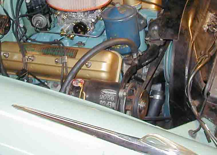
Here's what we start with: Disconnect the battery (-) cable, remove the Field and Armature wires from the generator
Remove the generator, disconnect the BAT wire from the Voltage Regulator
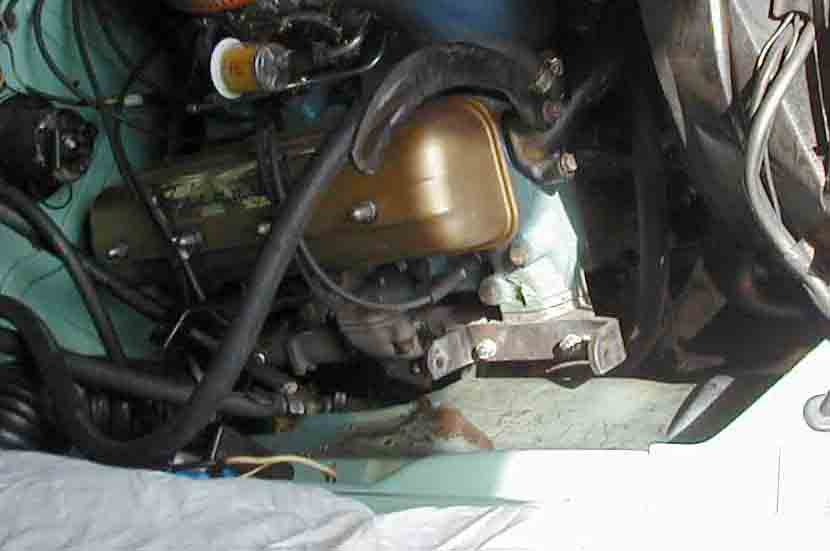
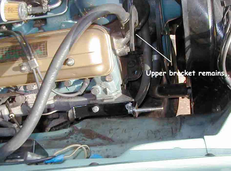
Remove the Generator mount. If you have an
extra, use it to modify or just be careful not to damage the existing one
when making these modifications.
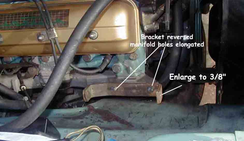
This is NOT a precision modification
Use a 5/16" drill to make an additional hole approximately 7/16" rearward
from each existing mount point. Connect the holes by using a scroll saw
and file the sides smooth. The idea is to create a slot to enable the
bracket to slide back and forth, when required to set the pulley alignment
for the fan belt.
Enlarge the (now) front generator mount hole to 3/8"
Turn the mount backwards and test fit until it slides fairly easy for the length of the slot. The slots do NOT have to be equal in size. You just need some wiggle room to adjust the pulley alignment
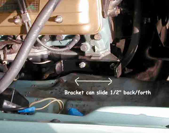
When a good fit is achieved, paint it up and loosely bolt it to the manifold.
Install a 2-3" 3/8" grade 8 bolt to the front upper mount hole.
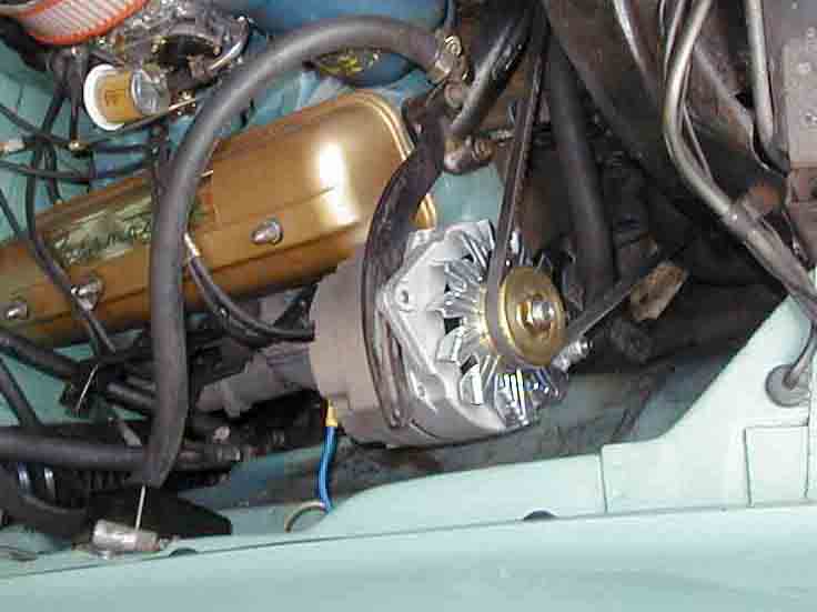
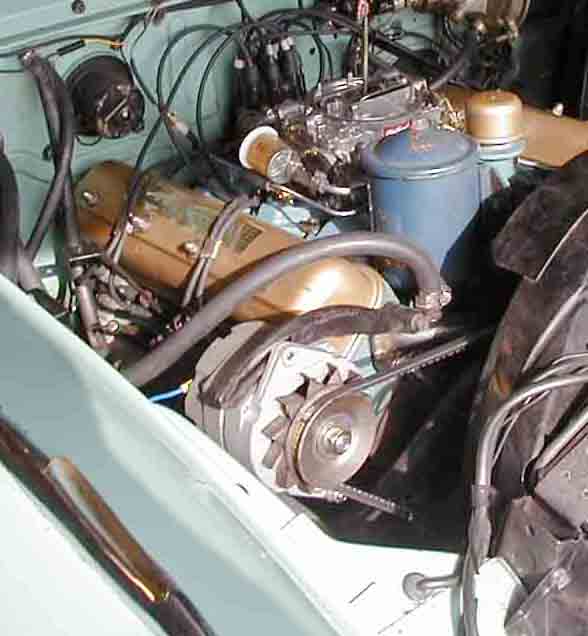
Mount the alternator on the 3/8" stud bottom mount. Slide the bracket forward until the pulleys align. Lower the upper bracket from the Stude generator. It should align right up. Install the original fan belt. Tighten all mount bolts/nuts
I replaced the new alternator pulley with the original generator pulley to lower the charge rate
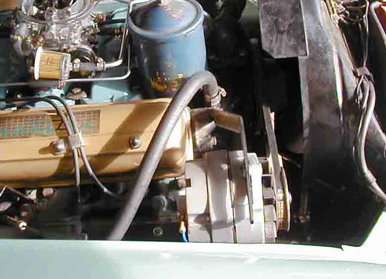
Looks like it was made for the car....
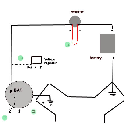
Wiring:
I- Disconnect the (-) Battery cable
I1) Install Alternator on engine
I2) Connect t2 (field) to BAT terminal with a 6" piece of #12 wire. One end uses a loop terminal, the other a female spade terminal
I3) Connect BAT to old #10 BAT terminal wire from the voltage regulator
I4) At the rear of the ammeter, connect a 12" piece of #10 from (-) to (+). This is important, if you want to read your ammeter. The original ammeter isn't designed for any more than 30 amps. The 53 amp alternator will 'peg' the ammeter, but the 'shunt' will allow more current to bypass the meter and still give you a decent reading. Without the shunt, it may overload your ammeter and burnout the coil, so it's better to do the loop routine.
Reconnect and tighten the (-) Battery cable.
Start the engine, the shunt wire should excite the regulator to start charging. You may have to rev it a bit.
NOTE:If you have to rev it more than you'd like, then remove the shunt wire from the BAT terminal and attach it somewhere under the dash, near where the buss splits. this way, the remote sense of the voltage requirements will send a quicker signal to the regulator
Also, see the Hawk Installation