
Bob's Resource Website (2007)
(Upper and lower outer Trunnion Install)
Oct 2000
The reason for using the tool is twofold. It creates an artificial fixed point,
where the cap screws onto the trunnion pin AND holds the control arm ears apart to
prevent collapse when tightening the caps.
When you torque the caps onto the assembly, what is taking place, is that you are, initially screwing the caps onto the pins. In the process, the outer threads on the cap are dragged through the control arm ear and score into the soft metal.
Greetings,
Here's my simple alignment prodecure
Also see the file on INNER Rubber bushings..
Kent - Moore tool, J-2044,
Kent - Moore tool J-2043. They are tools that Studebaker used to spread the outer ends of the upper and lower control arm,
prior to installing new trunnions. 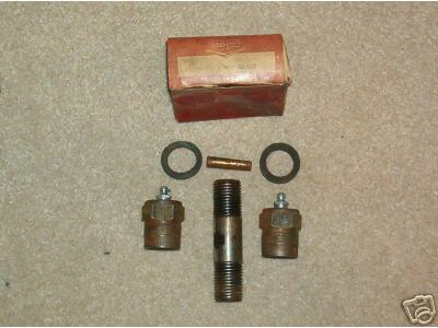
A lower, outer pin kit 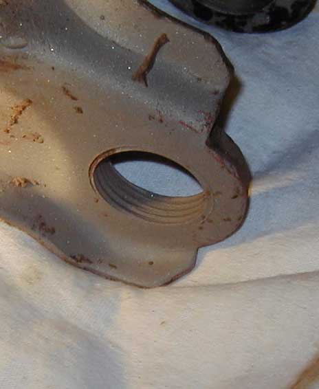
The outside of the hardened steel cap has large, blunted, threads which score into soft steel of the control arm ears. Note: The inner loop of NOS control arms are smooth and not marked until a trunnion cap is screwed onto the pin
Control arms can be reused, once or twice, however, every time a new cap is screwed into the ear, the threads are galled into the metal, by force. There will become a time, where there isn't sufficient grip left to support holding the required torque.
By using the spreader tool, you (A) LIMIT the amount of travel the cap can move inward on the pin, as the spreader is preventing the ear from bending inward and (B) cause the torque to be applied to the inside thread ramp of the trunnion pin and the outside thread ramp of the (inside of the) cap.
(You cannot turn the pin in the cap, with the spreader tool, in place)
When you release the spreader tool, the ears come together slightly (.015) and relieve the torque which was applied to the pin, allowing the pin to rotate, with the caps firmly set in the control arm ears by the (torqued) interference fit.
If you torque the caps onto ears WITHOUT using the spreader tool, then you're
pinching the pin in between everything. Since the pin is held fast by the
kingpin pinch bolt that maintains the alignment, everytime the suspension
travels up and down, the entire assembly will rotate, cap included. Since
the control arm can't rotate, the cap will move inside the ear to take
up the motion of the suspension, pivoting inside the ear, eventually wearing
excess clearance between the cap and ear and will eventually beat it bigger
as the damage progresses.
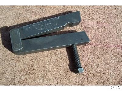
The following is a method to satisfy the requirement using a home-made tool,
thanks to Jack Vines
I made a useable spreader from two pieces of 3/4" square bar stock 1' long ,
a 1" long 3/8" bolt/nut/2washers and a C-clamp. Place the bar stock side by
side with bolt/nut/washers about 2" from one end, with the washers outside
the bar stock. Tighten the nut finger tight. This holds the bar stock
parallel. Put the short end between the ends of the A-arm. Put the C-clamp
across the long ends in such a manner as it will pull them together.
Measure the distance between the A-arm ends. Tighten the C-clamp, the bolt
will act as a fulcrum and the short ends will open and spred the A-arm the
specified distance. Install the cross-pin caps and release the C-clamp.