
Bob's Resource Website (2007) 36237 MC prep (click images for more detail)
Editorial changes March 2020 (Procedure is the same / application is modified)
|
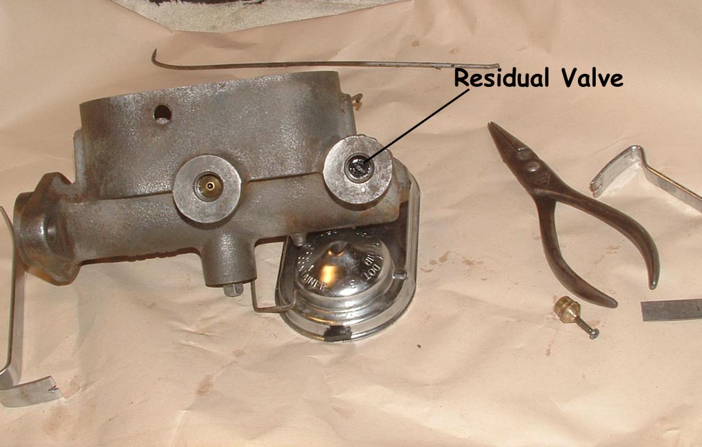
Most all Drum Brake master cyinders HAVE residual valves built into them. Their function is to maintain a certain fluid pressure on the brake lines AFTER you have removed your foot from the pedal. This residual pressure holds the brake linings closer to the friction surface, so you don't have to push the pedal too far, the NEXT time you hit the brakes. Each application is going to be different, due to the strength of the brake springs, whether or not your MC is above or below the brake cylinder, if you're changing to front disk brakes, or just upgrading to a dual MC on any Studebaker, etc. This is the process to remove the residual valves if necessary, on a 36237 master cylinder. On my application, it was for an underfloor MC replacement on a GT Hawk that already had Factory Disk Brakes (now Turner brakes).. Happy motoring/ RJ
|
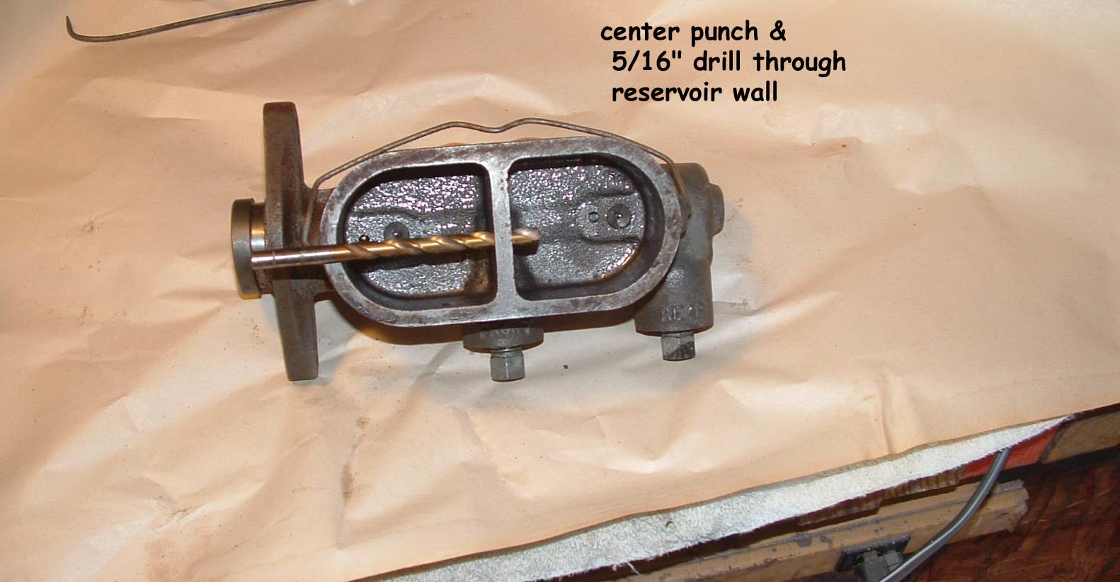 |
Start with a NAPA 36237Rebuilt Master Cylinder Punch and Drill a 5/16" hole between the wall of the reservoirs. This will allow the remote fill in the one side to maintain the fluid level in both sides. (click images for more detail) |
|
|
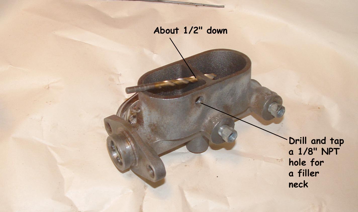
Hole should be around 1/2" down the wall. Go deeper if you can without gouging the outer wall. (click images for more detail) |
|
|
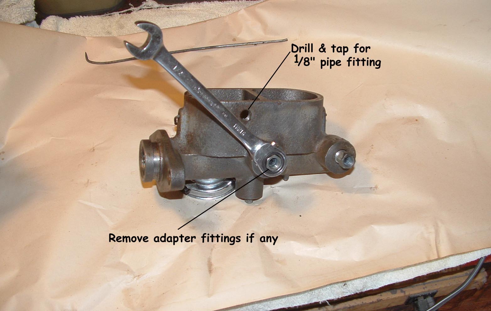
Drill and tap a 1/8 NPT hole for a filler neck or thread another brass fitting to use all metal connectors Remove the line adapters if present. (click images for more detail) |
|
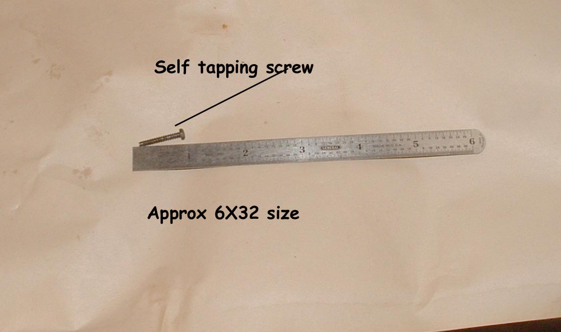 |
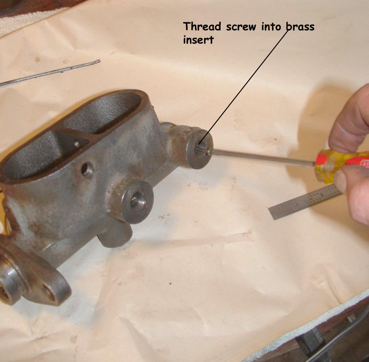
Find a self tapping screw, approximately 6/32/phillips head. (click images for more detail) |  |
|
Start the screw into the insert and give it about 3 turns. (click images for more detail) |
|
|
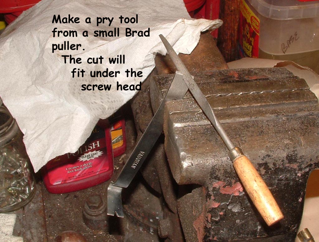
you'll need a pry tool and a small brad puller will do fine. You have to file a slot to fit under the screw head. (click images for more detail) |
|
|
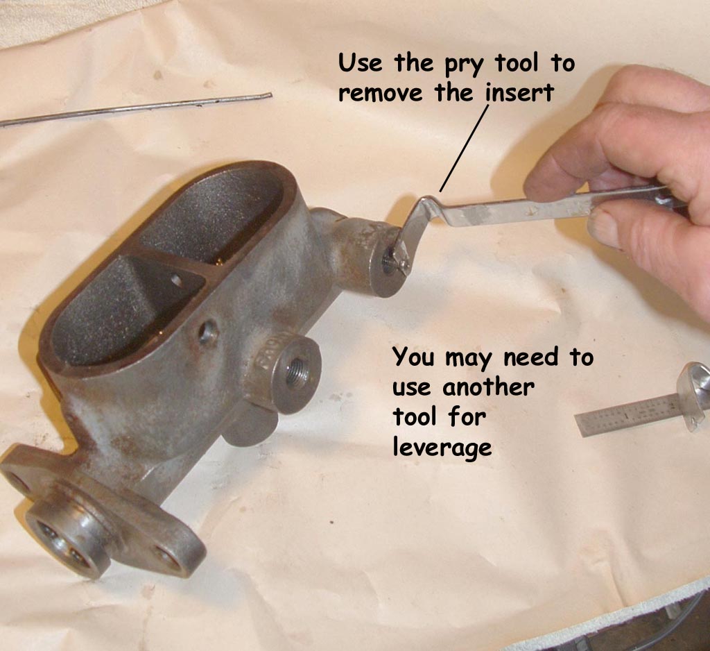
Use the tool under the screw. Too much force will strip the screw out of the insert. (click images for more detail) |
|
|
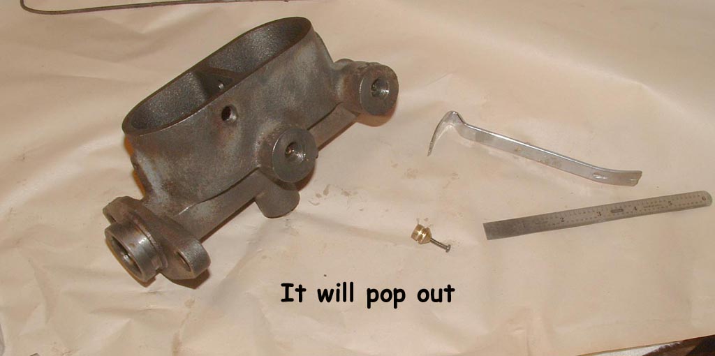
With a little patience and persistance, the insert will pop out. (click images for more detail) |
|
|
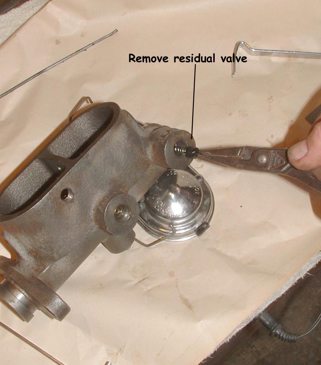
..Exposing the rubber residual valve behind the insert. These are the valves you have to remove, to use the Turner Dual Master system. (click images for more detail) |
|
|
A slight tug removes the valve (click images for more detail) |
|
|
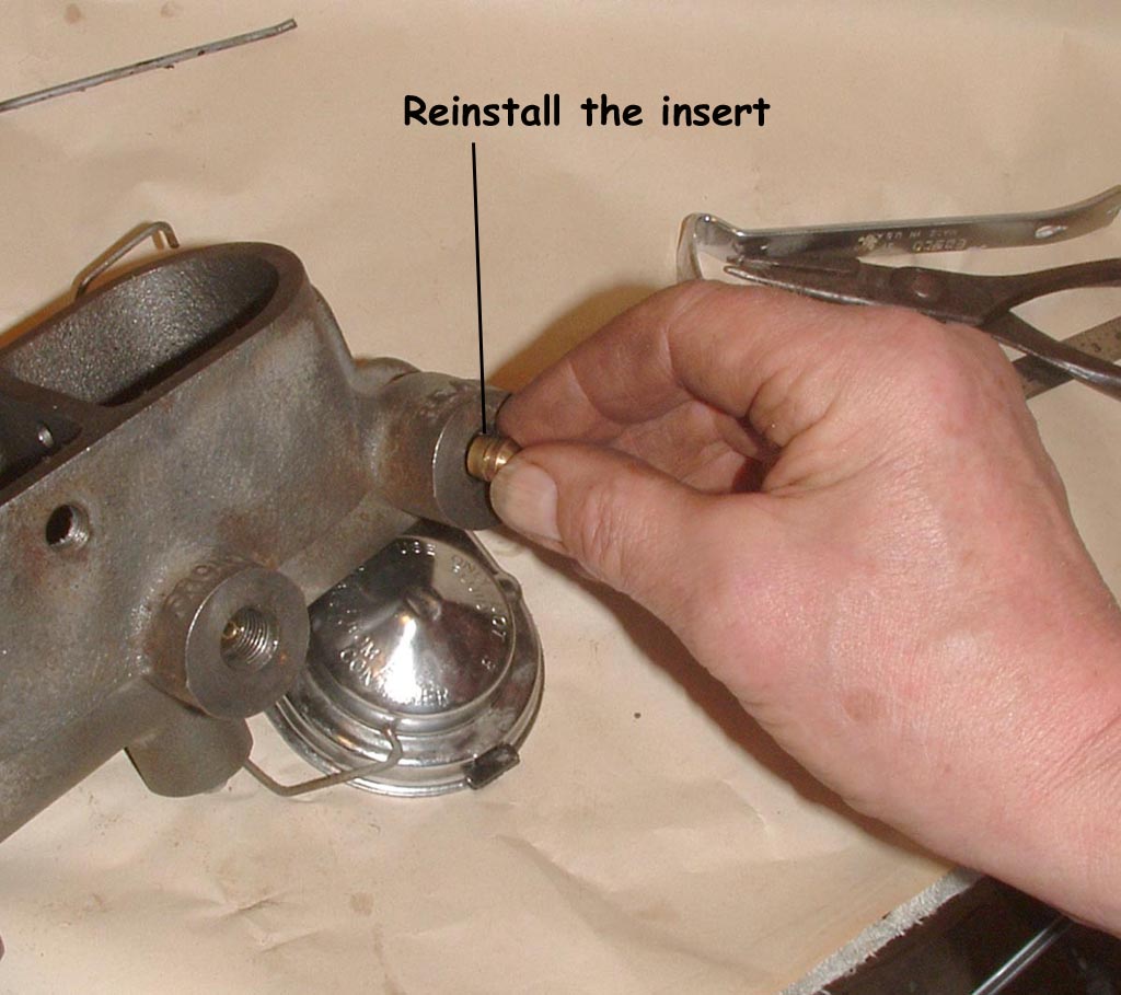
Replace the insert in the port (click images for more detail) |
|
|
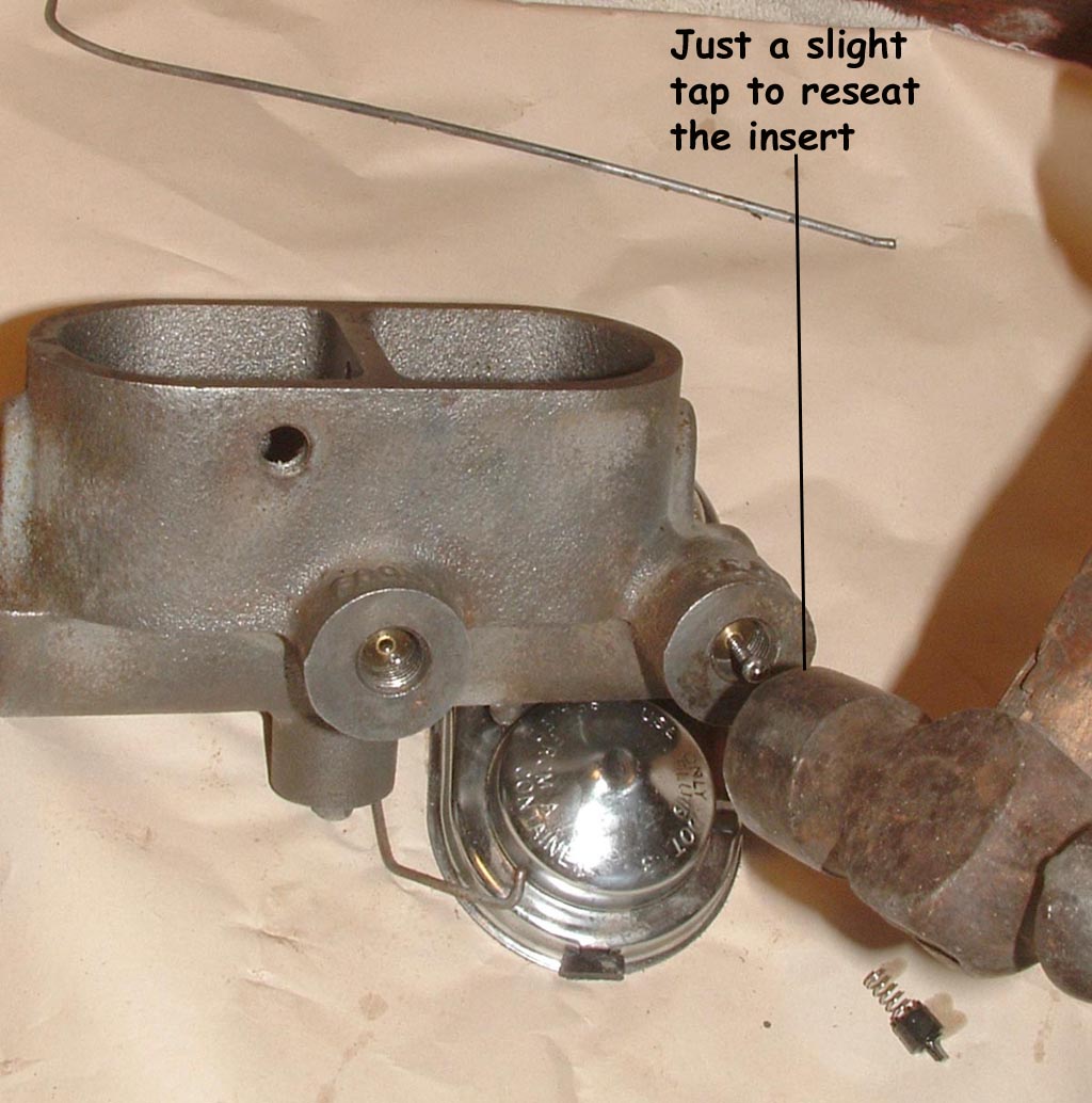
tap just slightly to start it (click images for more detail) |
|
|
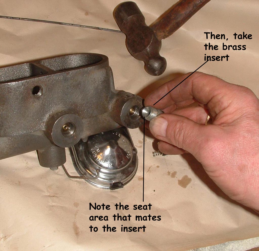
Remove the helper screw from the insert, then take the adapter and notice how the inner face mates with the insert (click images for more detail) |
|
|
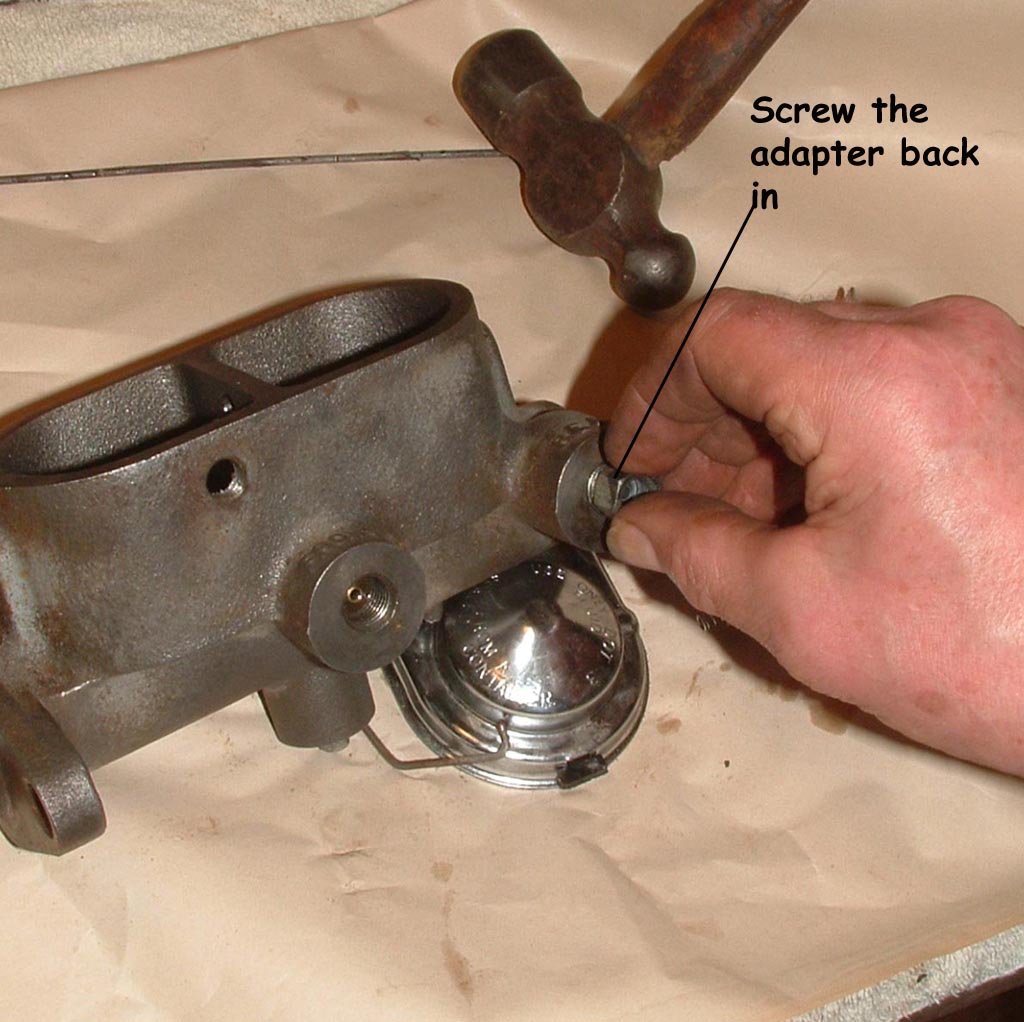
Take the adapter and start it back into the port (click images for more detail) |
|
|
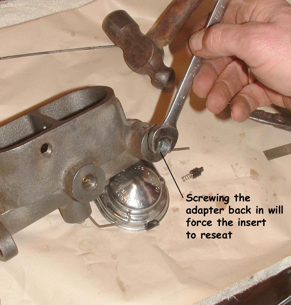
Tighten slowly to assure the insert isn't twisted in the port. Snug it up and repeat the procedure on the other port (click images for more detail) |
|
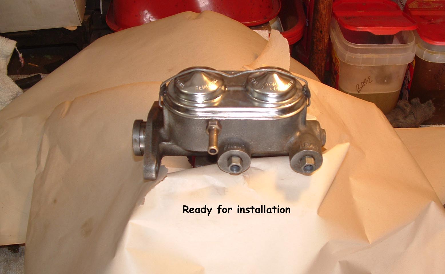 |
Install the filler hardware and the cap / The unit is now ready to be bench bled and installed on the car. (click images for more detail) |
![]()
Some technical opinions are my own from experience, other informational data is from online sources with credits when available and while care has been taken to be as accurate as possible, it is offered only as a guide and caution should be exercised in the application of it.